Model 8903B
J
Service
Special
Function
1.11
1
.a
1.5
1.1
TROUBLESHOOTING
Total
Change
in Oscilloscope
Vertical Gain Minimum Maximum
XI
4.9
5.1
Xl
1.2 1.3
x10
3.0
3.3
XlOO
4.8 5.2
Amplitude Limits
(divisions
pk-pk)
General
Procedures for checking the measurement circuits of the instrument are given below. The blocks
or
points
to
check are marked on the block diagram by
a
hexagon with
a
check mark and a number inside, for example
(J3)
.
The procedures assume that the source
is
working properly.
A
second audio source
is
needed only
if
distortion
is
out of specification and it cannot be determined whether the instrument’s source
or
distortion measurement
is
at fault. Before performing any check, perform all the checks on Service Sheet BD1.
Equipment
Audio Analyzer..
...............
HP 8903B
or
HP
339A
Oscilloscope.
...............................
HP 1740A
Input Amplifier Check
NOTE
This check does not test the Over-Voltage Protection.
If
the Over-Voltage
Protection
is
suspected to be faulo, see Service Sheet
1.
1.
On the Audio Analyzer, key in 41.0 SPCL to initialize the instrument. Set the INPUT and OUTPUT switches
to
ground. Set IMPEDANCE
to
600R. Key
in
AMPTD 3
V.
Connect the HIGH OUTPUT to the HIGH INPUT
through a tee adapter.
2.
Connect a high-impedance, ac coupled oscilloscope to the tee
at
the HIGH INPUT. Use the oscilloscope’s
vertical gain controls to adjust the display amplitude for
5
divisions peak-to-peak deflection
of
the sinusoidal
signal. (The period
of
the signal should be
1
ms.)
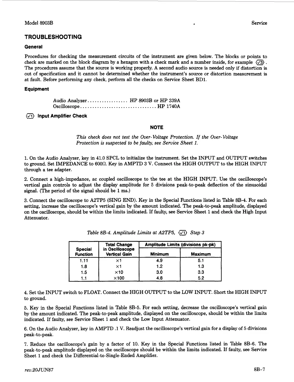
3. Connect the oscilloscope to A2TP5 (SING END). Key in the Special knctions listed in Table 8B-4.
For
each
setting, increase the oscilloscope’s vertical gain by the amount indicated. The peak-to-peak amplitude, displayed
on the oscilloscope, should be within the limits indicated.
If
faulty, see Service Sheet
1
and check the High Input
Attenuator.
4. Set the INPUT switch to FLOAT. Connect the HIGH OUTPUT to the
LOW
INPUT. Short the HIGH INPUT
to
ground.
5.
Key in the Special Functions listed in Table
8B-5.
For each setting, decrease the oscilloscope’s vertical gain
by the amount indicated. The peak-to-peak amplitude, displayed on the oscilloscope, should be within the limits
indicated.
If
faulty, see Service Sheet
1
and check the Low Input Attenuator.
6. On the Audio Analyzer, key in AMPTD
.1
V.
Readjust the oscilloscope’s vertical gain for a display of
5
divisions
peak-to-peak.
7.
Reduce the oscilloscope’s gain by a factor of 10. Key in the Special hctions listed in Table 8B-6. The
peak-to-peak amplitude displayed on the oscilloscope should be within the limits indicated.
If
faulty, see Service
Sheet
1
and check the Differential-to-Single-Ended Amplifier.
rev.20JUN87
8B-7
 Loading...


