Service Model 8903B
Total Change
Special in Oscilloscope
Function Vertical Gain
1.1
xl
1.5
+lO
1.8
+loo
1.11
+loo
Amplitude Limits (divisions pk-pk)
Minimum Maximum
4.8 5.2
3.0 3.3
1.2 1.3
4.9 5.1
Table
8B-6.
Amplitude Limits at A2TP5,
a
Step
7
Total Change
Special in Oscilloscope
Function Vertical Gain
1.11
xl
1.12
xl
1.13
+lo
1.14
+lo
Amplitude Limits (divisions pk-pk)
Special
Function Minimum Maximum
1.17
1.19 4.8
5.2
Amplitude Limits (divisions pk-pk)
Minimum Maximum
4.8
5.2
7.7 8.2
1.2 1.3
1.9 2.1
’
8.
On the Audio Analyzer, key in
1.11
SPCL. On the oscilloscope, set the gain back
to
xl.
(Check that the
waveform is still
5
divisions peak-to-peak.)
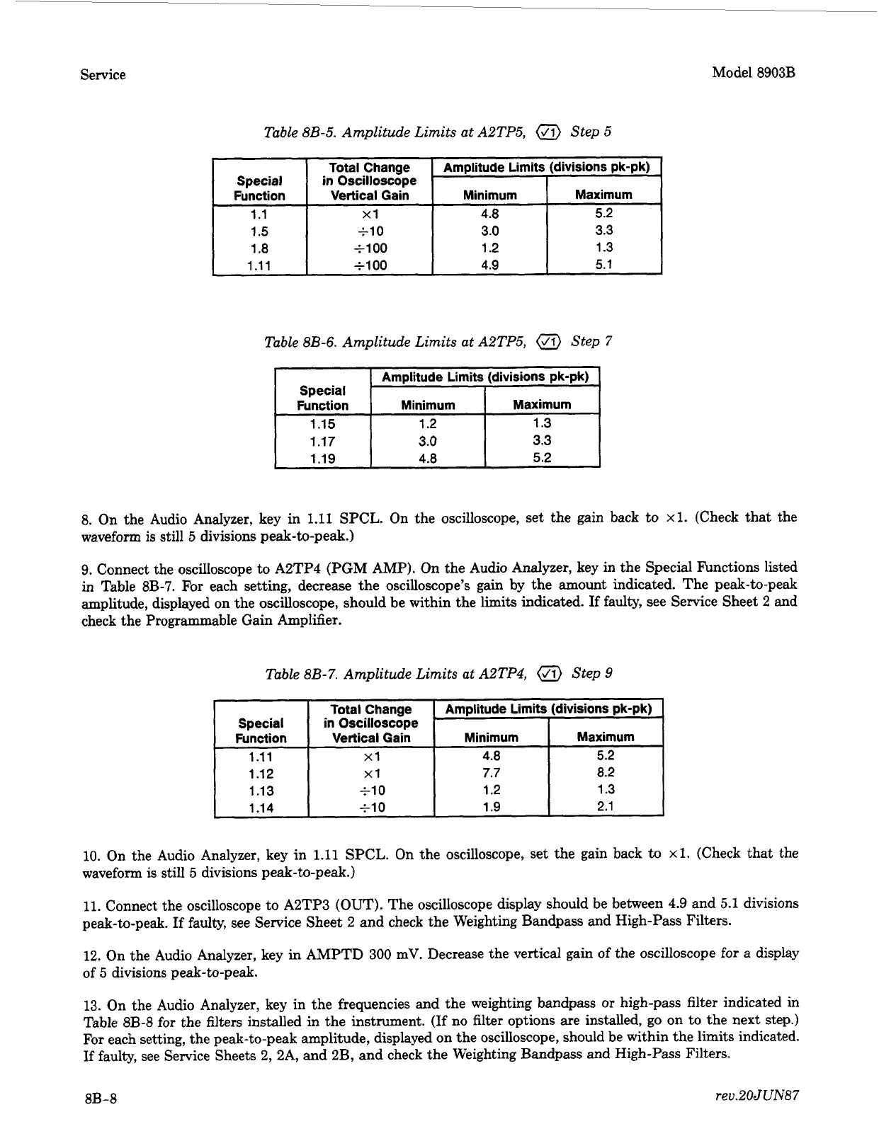
9. Connect the oscilloscope to A2TP4 (PGM AMP). On the Audio Analyzer, key in the Special Functions listed
in Table 8B-7.
For
each setting, decrease the oscilloscope’s gain by the amount indicated. The peak-to-peak
amplitude, displayed on the oscilloscope, should be within the limits indicated.
If
faulty, see Service Sheet
2
and
check the Programmable Gain Amplifier.
Table
8B-7.
Amplitude Limits at A2TP4,
a
Step
9
10. On the Audio Analyzer, key in
1.11
SPCL.
On
the oscilloscope, set the gain back to
xl.
(Check that the
waveform
is
still
5
divisions peak-to-peak.)
11.
Connect the oscilloscope to A2TP3 (OUT). The oscilloscope display should be between
4.9
and 5.1 divisions
peak-to-peak.
If
faulty, see Service Sheet
2
and check the Weighting Bandpass
and
High-Pass Filters.
12.
On the Audio Analyzer, key in AMPTD
300
mV. Decrease the vertical gain of the oscilloscope for a display
of
5
divisions peak-to-peak.
13. On the Audio Analyzer, key in the frequencies and the weighting bandpass
or
high-pass filter indicated in
Table
8B-8
for the
filters
installed in the instrument.
(If
no filter options are installed, go on to the next step.)
For
each setting, the peak-to-peak amplitude, displayed on the oscilloscope, should be within the limits indicated.
If
faulty, see Service Sheets 2, 2A, and 2B, and check the Weighting Bandpass and High-Pass Filters.
8B-8
rev.20JUN87