Service
Model 8903B
Weighting Filter
CCllR WEIGHTING
CCIR/ARM WEIGHTING
“A”
WEIGHTING
Table 8B-8. Amplitude Limits at A2TP3,
(J1)
Step
13
Amplitude Limits (divisions)
Minimum Maximum
0.9’ 1.1’
5.1
5.4
3.0
3.2
Weighting Bandpass
or
High-Pass
Filter
400
HZ HIGH-PASS
CCllT WEIGHTING
CCIR WEIGHTING
C-MESSAGE WEIGHTING
CCIR/ARM WEIGHTING
‘A”
WEIGHTING
Source
Frequency
(Hz)
1
000
400
800
300
3
000
6
300
200
10
000
1
000
500
3
000
6
300
200
10
000
1
000
200
10
000
Amplitude Limit!
Minimum
4.9
2.5
4.8
1.2
2.2
2.0’
0.9
1.2‘
4.9
1.8
3.1
1
.O‘
0.5
6.2
4.9
1.3
3.4
[divisions pk-pk)
Maximum
5.1
4.5
5.2
1.8
3.1
2.1’
1.1
1.4’
5.1
2.5
4.5
1.1’
0.6
7.1
5.1
1.5
4.1
14.
On the Audio Analyzer, set the Weighting Bandpass or High-Pass Filter
off
if
one
is
on. Key in
FREQ
1
kHz
and AMPTD
1
V.
Connect the oscilloscope
to
A2TP4
(PGM
AMP). Adjust the oscilloscope’s vertical gain for
7.1 divisions peak-to-peak amplitude.
15.
DC couple the oscilloscope and connect
it
to
A2TP2
(RMS).
The waveform should be a dc voltage between
2.4
and
2.6 divisions (with respect to ground).
If
faulty, see Service Sheet 2
and
check the Input Range Detector.
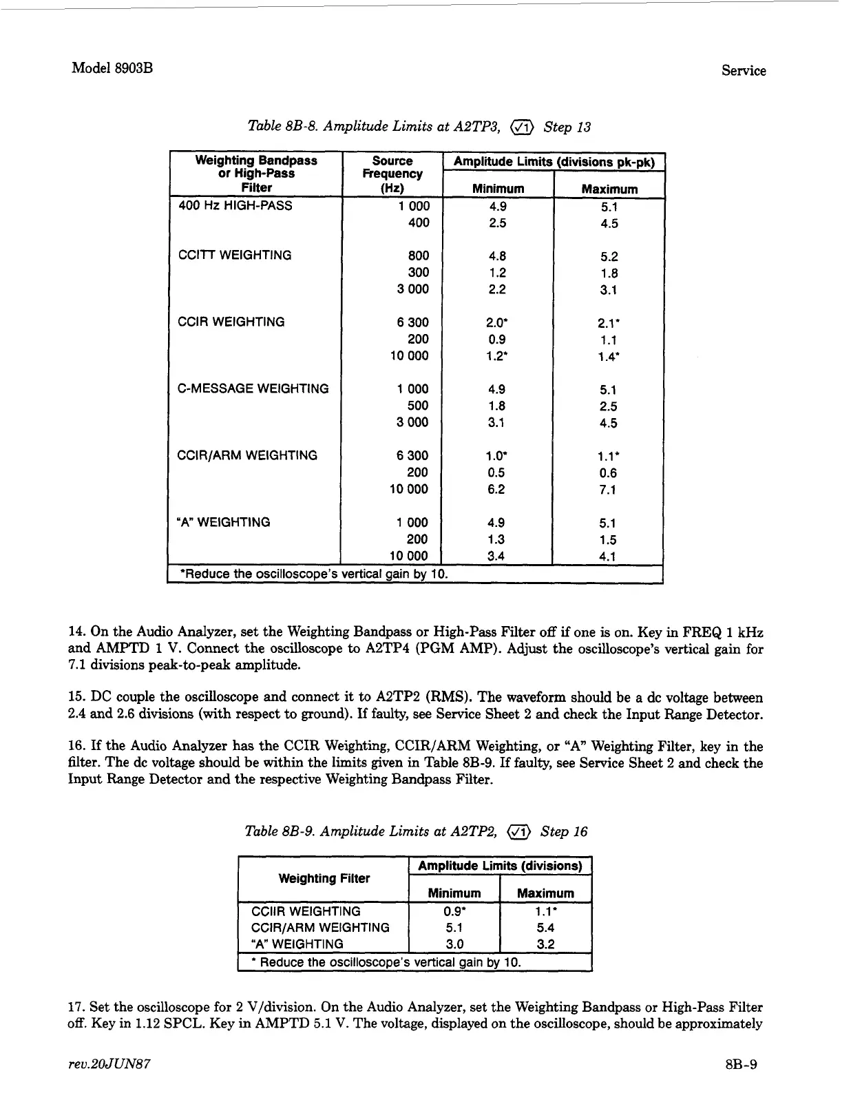
16.
If the Audio Analyzer has the CCIR Weighting, CCIR/ARM Weighting, or “A” Weighting Filter, key in the
filter. The dc voltage should be within the limits given in Table 8B-9. If faulty, see Service Sheet 2 and check the
Input Range Detector and the respective Weighting Bandpass Filter.
Table 8B-9. Amplitude Limits at A2TP2, Step
16
17.
Set the oscilloscope for
2
V/division. On the Audio Analyzer, set the Weighting Bandpass or High-Pass Filter
off.
Key in
1.12
SPCL. Key in AMPTD
5.1
V.
The voltage, displayed on the oscilloscope, should be approximately
rev.2OJUN87
8B-9