Model
8903B
TROUBLESHOOTING---SERVICE
SHEET
3
A3TP5
4.8
to
7.2
0.3
to
0.5
0.3
to
0.5
4.8
to
7.2
Service
A3TP6
A3TP7 A3TP14
4.8
to
7.2
<1.2
4.8
to
7.2
1.6
to
2.4
4.8 to 7.2 <0.1
1.6
to
2.4
4.8
to
7.2 <1.2 4.8
to
7.2
<0.1 4.8
to
7.2
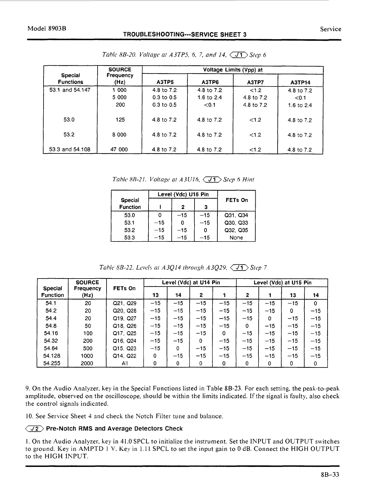
Tahk
8,920.
Voltagc
ut
A3TPS.
6,
7,
and
14,
a
Sfcp
6
Level (Vdc) U16 Pin
I
Special
1
I
I
Special
Functions
FETs
On
Function
53.0
SOURCE
Frequency
(Hz)
1
000
5
000
200
I
2
3
0
-15 -15 Q31,
Q34
53.1 and 54.147
53.1
53.2
53.3
53.0
53.2
53.3 and 54.108
-1
5
0
-15 Q30, Q33
-15 -15
0
Q32, Q35
-15 -15
-15 None
125
Level (Vdc) at U14 Pin
4.8
to
7.2
I
<1.2
1
4.8 t07.2
Level (Vdc)
at
U15
8
000
4.8
to
7.2
47
000
I
4.8
to
7.2
I
4.8
to
7.2
I
4.2
I
4.8 to72
TahlLi
8/3-22.
Lcvcl,
ul
A3Q14
fhroirgh
A3Q2Y,
-Step
7
SOURCE
Frequency
20
20
20
50
100
200
500
1000
2000
(H4
Din
Special
Function
54.1
6
54.32
54.64
54.128
54.255
14
I
14
-15
,
-15
-1
5
-1
5
-1
5
-1
5
0
-1
5
0
2
1
-1
5
-1
5
-1
5
-1
5
:_I
0
13
13
-1
5
-1
5
-1 5
-1
5
-1 5
-1 5
-1
5
0
0
2
-1 5
-1
5
-1 5
-1 5
-1
5
0
-1
5
-1
5
0
Q21, Q29
(220, Q28
Q19, a27
Q18, Q26
(217, Q25
(216, Q24
Q15, Q23
Q14, Q22
All
-1 5
-1
5
-1
5
0
-15
-1
5
-1
5
-1
5
0
-1
5
0
-1
5
-1 5
-1 5
-1
5
-1 5
-1
5
0
0
-1
5
-1 5
-1 5
-1
5
-1
5
-1
5
-1
5
0
-1 5
-1
5
-1
5
9.
On the Audio Analyzer,
key
in
the
Special Functions listed in Table 8B-23. For each setting. the peak-to-peak
amplitude, observed on the oscilloscope, should be within the limits indicated.
If
the signal is faulty,
also
check
the control signals indicated.
10.
See Service Sheet
4
and check the Notch
Filter
tune and balance.
a
Pre-Notch
RMS
and Average Detectors Check
1.
On
the Audio Analyzer, key
in
41.0
SPCL
to
initialize the instrument. Set the INPUT and OUTPUT switches
to
ground. Key in AMPTD
1
V.
Key
in
1.1
1
SPCL to set the input gain to
0
dB. Connect the
HIGH
OUTPUT
to the
HIGH
INPUT.
8B-33