Service
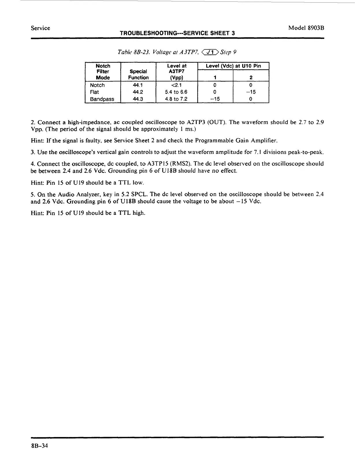
Notch
Filter
Model 8903B
TROUBLESHOOTING---SERVICE SHEET
3
Level
at
Level
(Vdc) at
U10
Pin
Special
A3TP7
I
Mode
Notch
Flat
Band
pass
Function (VPP)
1
2
44.1
c2.1
0 0
44.2
5.4
to
6.6
0
-1
5
44.3
4.8
to
7.2
-1
5
0
2. Connect a high-impedance, ac coupled oscilloscope
to
A2TP3 (OUT). The waveform should be 2.7
to
2.9
Vpp. (The period of the signal shoiild be approximately
1
ms.)
Hint:
If
the signal is faulty.
see
Service Sheet 2 and check the Programmable Gain Amplifier.
3.
Use the oscilloscope’s vertical gain controls
to
adjust the waveform amplitude for
7.1
divisions peak-to-peak.
4. Connect the oscilloscope, dc coupled,
to
A3TP15
(RMS2).
The
dc
level
observed on the oscilloscope should
be between 2.4 and
2.6
Vdc. Grounding pin
6
of
U18B should have
no
effect.
Hint: Pin 15
of
U19 should be a
TTL
low.
5.
On
the Audio Analyzer, key in
5.2
SPCL. The dc level observed on the oscilloscope should be between 2.4
and 2.6 Vdc. Grounding pin 6
of
U18B should cause the voltage
to
be
about
-
15 Vdc.
Hint: Pin 15
of
U19 should be a
TTL
high.
8B-34