Service Model 89038
TROUBLESHOOTING
TROUBLESHOOTING---SERVICE SHEET
5
Special
Function
3.1
3.3
General
Procedures for checking the Output Amplifier/Voltnieter Assembly are given below. The circuits or points to
check are marked on the schematic diagram by a hexagon with a check mark and a number inside, for example,
m.
In addition, any points outside the labeled circuit area that must be checked are also identified. Fixed
signals are shown on the schematic also inside a hexagon, for example,
<
+1.9
TO
+2.1
VDC
).
Extend the
board assembly where necessary to make measurements. These procedures assume that the source in working
properly.
Equipment
Level at
Level
(TTL)
at
U21
Pin
A4TP8 (mVpp)
1
8
16
140
to
160
H
L L
1400
to
1600
L
H
H
Oscilloscope
.
.
.
.
. .
. . .
.
. .
.
.
.
.
.
. .
.
. . .
. . .
.
. . .
HP
1740A
a
Attenuators, Amplifiers, and Low-Pass
Filters
Check
1.
On
the Audio Anlayzer, key in 41.0 SPCL to initialize the instrument. Set the INPUT and OUTPUT switches
to
ground. Key in AMPTD
100
mV. Key in
1.11
SPCL
to
set the input gain
to
0
dB. Connect the HIGH
OUTPUT to the
HIGH
INPUT.
2. Connect a high-impedence, ac coupled oscilloscope to A3TP7 (OUT). Increment the Audio Analyzer's
SOURCE amplitude for exactly 300 mVpp
on
the oscilloscope.
Hint: The amplitude at A3TP7 before adjustment should be between 260 and 300 mVpp. (The period should
be approximately
1
ms.)
If
the signal is faulty, see Service Sheet
3
and check the Notch Filter.
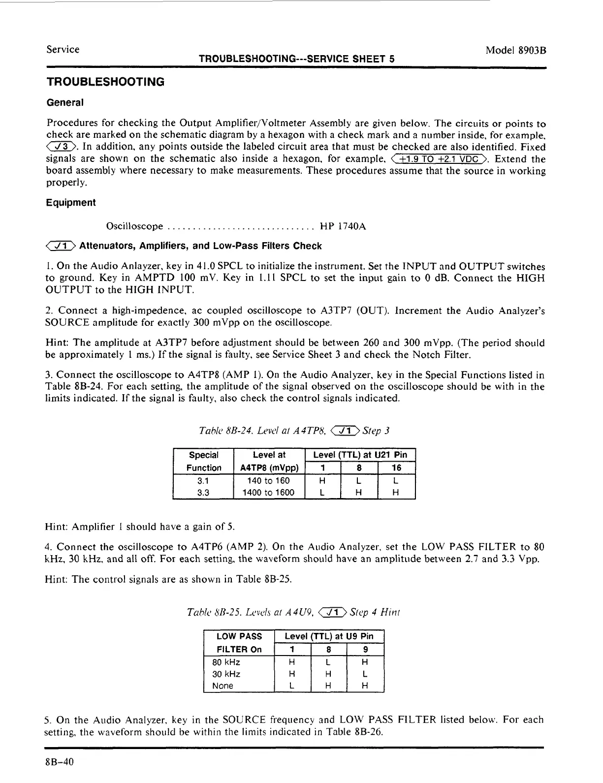
3. Connect the oscilloscope to
A4TP8
(AMP
1).
On
the Audio Analyzer,
key
in the Special Functions listed in
Table 8B-24. For each setting, the amplitude of the signal observed
on
the oscilloscope should be with in the
limits indicated. If the signal is faulty, also check the control signals indicated.
Tahlc
8B-24.
Levd
al
A4TP8,
Slcp
3
Hint: Amplifier
1
slioLtld have a gain of 5.
4. Connect the oscilloscope
to
A4TP6
(AMP
2). On the Audio Analyzer, set the LOW PASS FILTER to
80
kHz.
30
kHz,
and all off.
For
each setting, the waveform should have an amplitude between 2.7 and
3.3
Vpp.
Hint: The control signals are as shown in Table 8B-25.
Tahk
813-25.
Levcls
ai
A
4U9,
Sicy
4
Hinr
FILTER
On
80
kHz
30
kHz
H
H
None
L
H
Y
H
5.
On
the Audio Analyzer,
key
in the
SOURCE
frequency and
LOW
PASS
FILTER listed below.
For
each
setting, the waveform should be within the limits indicated
in
Table 8B-26.
8B-40
 Loading...


