Service
Model 8903B
TROUBLESHOOTING---SERVICE SHEET
5
Tabk
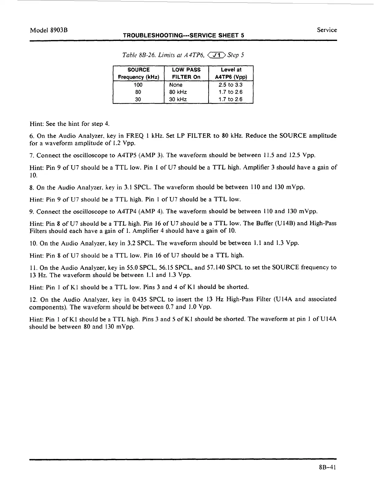
813-26.
Limits
at
A4TP6,
a
Sty
5
SOURCE
LOW
PASS
Level
at
2.5
to
3.3
80
kHz 1.7
to
2.6
30
kHz
1.7
to
2.6
Hint: See the hint for
step
4.
6.
On the Audio Analyzer, key in FREQ 1 kHz. Set LP FILTER
to
80
kHz. Reduce the SOURCE amplitude
for a waveform amplitude
of
1.2 Vpp.
7. Connect the oscilloscope to A4TP5 (AMP 3). The waveform should be between
11.5
and
12.5
Vpp.
Hint: Pin
9
of U7 should be a TTL low. Pin
1
of
U7 should be a TTL high. Amplifier
3
should have a gain of
10.
8.
On
the Audio Analyzer,
key
in
3.1
SPCL. The waveform should be between 110 and
130
rnVpp.
Hint: Pin
9
of
U7 should be a TTL high. Pin
1
of
U7 should be a TTL low.
9.
Connect the oscilloscope to A4TP4 (AMP 4). The waveform should be between 110 and 130 mVpp.
Hint: Pin
8
of
U7 should be a TTL high. Pin 16 of U7 should be a TTL
low.
The Buffer (U14B) and High-Pass
Filters should each have a gain of
1.
Amplifier 4 should have a gain
of
10.
10. On the Audio Analyzer, key in 3.2 SPCL. The waveform should
be
between 1.1 and 1.3 Vpp.
Hint: Pin 8
of
U7 should be a TTL low. Pin 16 of U7 should
be
a TTL high.
11. On the Audio Analyzer,
key
in
55.0
SPCL, 56.15 SPCL, and 57.140 SPCL
to
set
the SOURCE frequency
to
13
Hz. The waveform should be between
1.1
and
1.3
Vpp.
Hint: Pin
1
of K1 should be a TTL low. Pins
3
and 4 of K1 should be shorted.
12. On the Audio Analyzer,
key
in 0.435 SPCL
to
insert the 13 Hz High-Pass Filter (U14A and associated
components). The waveform shoiild be between 0.7 and
1.0
Vpp.
Hint: Pin
1
of K1 should be a TTL high. Pins
3
and
5
of
K1
should be shorted. The waveform at pin
1
of U14A
should be between 80 and 130 mVpp.
~
8B-4
1