Model 8903B Service
True
RMS
Average
Quasi-peak
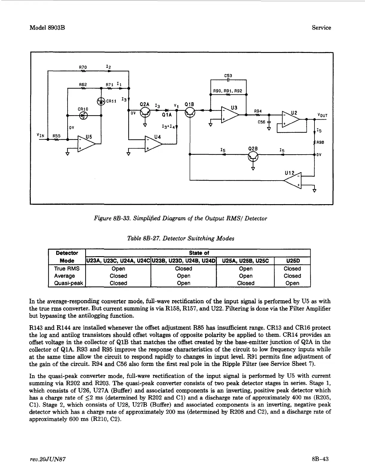
Figure
8B-33.
Simplified Diagram
of
the Output
RMS/
Detector
Open Closed Open Closed
Closed Open Open Closed
Closed
Open
Closed
Open
Table 8B-27. Detector Switching Modes
I
Detector
I
State
of
1
I
I
I
I
Mode IU23A, U23C, U24A. U24CIU23B. U23D. U24B. U24DI U25A. U25B. USC
f
U25D
I
In the average-responding converter mode, full-wave rectification
of
the input signal is performed by
U5
as
with
the true
rms
converter. But current summing
is
via R158, R157, and U22. Filtering is done via the Filter Amplifier
but bypassing the antilogging function.
R143 and R144 are installed whenever the offset adjustment R85 has insufficient range. CR13 and CR16 protect
the log and antilog transistors should offset voltages
of
opposite polarity be applied
to
them. CR14 provides an
offset voltage in the collector of Q1B that matches the offset created by the base-emitter junction of Q2A in the
collector of Q1A. R93 and
R95
improve the response characteristics
of
the circuit
to
low frequency inputs while
at the same time allow the circuit
to
respond rapidly
to
changes
in
input level. R91 permits fine adjustment
of
the gain of the circuit. R94 and C56 also form the first real pole
in
the Ripple Filter
(see
Service Sheet 7).
In the quasi-peak converter mode, full-wave rectification
of
the input signal
is
performed by U5 with current
summing via R202 and R203. The quasi-peak converter consists
of
two
peak detector stages in series. Stage
1,
which consists
of
U26, U27A (Buffer) and associated components
is
an inverting, positive peak detector which
has a charge rate
of
52 ms (determined by R202 and Cl) and
a
discharge rate of approximately 400 ms (R205,
Cl). Stage 2, which consists of U28, U27B (Buffer) and associated components is an inverting, negative peak
detector which has a charge rate
of
approximately 200 ms (determined by R208 and C2), and a discharge rate
of
approximately 600
ms
(R210, C2).
reu.20JUN87
8B-43