EL-MF877-00 Page 2
Template Revision B
PSG instructions for this template are available at EL-MF877-01
Tool Description Tool Size (if
applicable)
Screw driver 2#
3.0 Product Disassembly Process
3.1 List the basic steps that should typically be followed to remove components and materials requiring selective treatment:
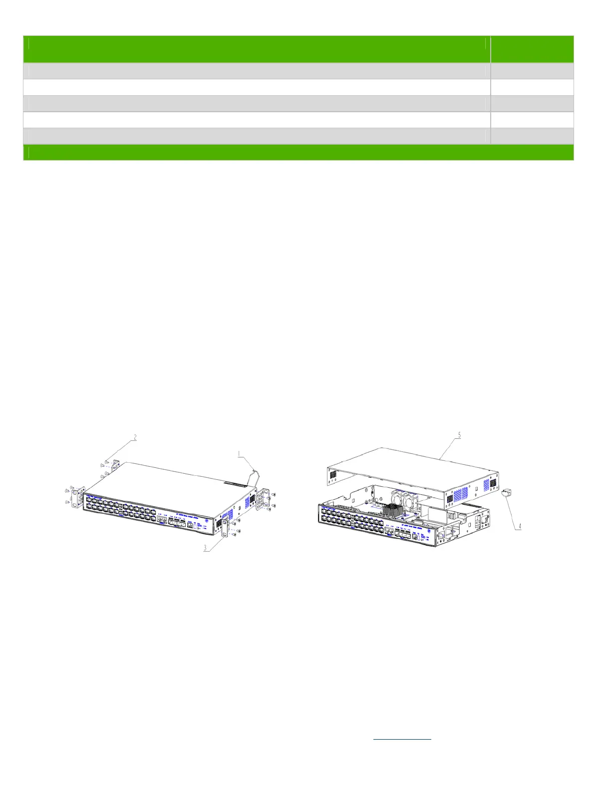
1. Unscrew the Power Cable Holder 1.
2. Unscrew all screws 2, and then remove the mounting angle 3.
3. Remove the part 4, and then remove top cover 5.
4. Remove all of the inner cables.
5. Unscrew all screws on Part 7, and then remove Part 7 from base 6.
6. Unscrew all screws on Part 8, and then remove Part 8 from base 6.
7. Unscrew all screws on fan 9, and then remove fan 9 from base 6.
8. Remove plastic panel 10 from the chassis.
9. Unscrew all screws on PCB 11, and then remove PCB 11.
10. Unscrew all screws on Part 12, and then remove Part 12 from base 6.
11. Remove all of the labels from the chassis.
12. Remove part 11-1 from PCB 11.
13. Unscrew the screws on PCB 11-3, and then remove PCB 11-3.
14. Unscrew part 11-2 from PCB 11-4, and then remove part 11-2.
3.2 Optional Graphic. If the disassembly process is complex, insert a graphic illustration below to identify the items
contained in the product that require selective treatment (with descriptions and arrows identifying locations).
Figure 1 Unscrew the Power Cable Holder 1 and screw 2 Figure 2 Remove Part 4 and Cover 5
 Loading...


