EasyManuals Logo

HP A7503 User Manual

HP A7503
63 pages
To Next Page IconTo Next Page
To Previous Page IconTo Previous Page
Page #7 background imageLoading...
Page #7 background image
3
Basic concepts
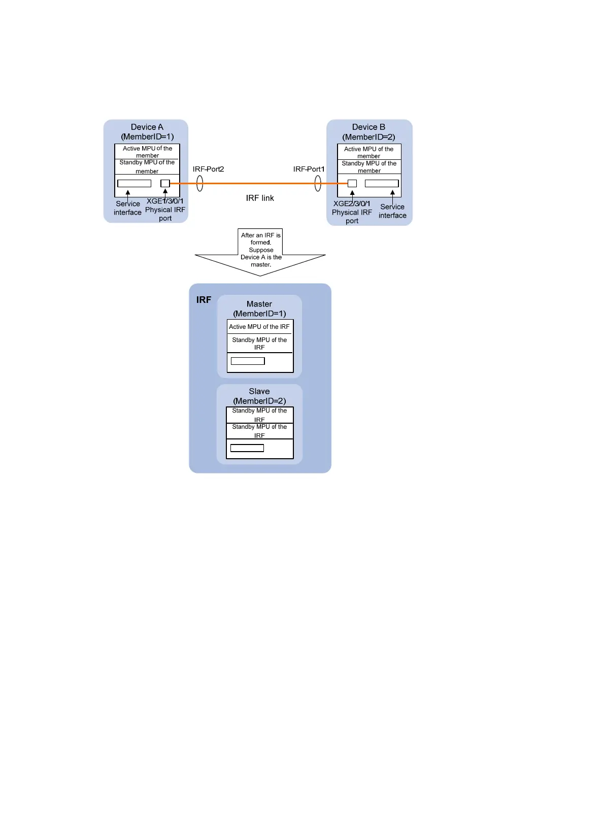
Figure 2 IRF implementation schematic diagram (with two member switches)
Device A and Device B in Figure 2 form an IRF fabric, which has four MPUs (one active and three standby)
and two interface cards. The IRF fabric manages both the physical and software resources of Device A
and Device B.
An IRF fabric with four member switches is larger in scale: it has eight MPUs (one active and seven
standby) and four interface cards, as shown in Figure 3.

Table of Contents

Questions and Answers:

Question and Answer IconNeed help?

Do you have a question about the HP A7503 and is the answer not in the manual?

HP A7503 Specifications

General IconGeneral
BrandHP
ModelA7503
CategorySwitch
LanguageEnglish

Related product manuals