Removal and Replacement Procedures
Maintenance and Service Guide 6–51
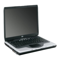
2. Use a 3/16-inch Hex socket wrench to remove the
2 HM3.0×10.0 screw locks on each side of the external
monitor connector.
Removing the System Board Screw Locks
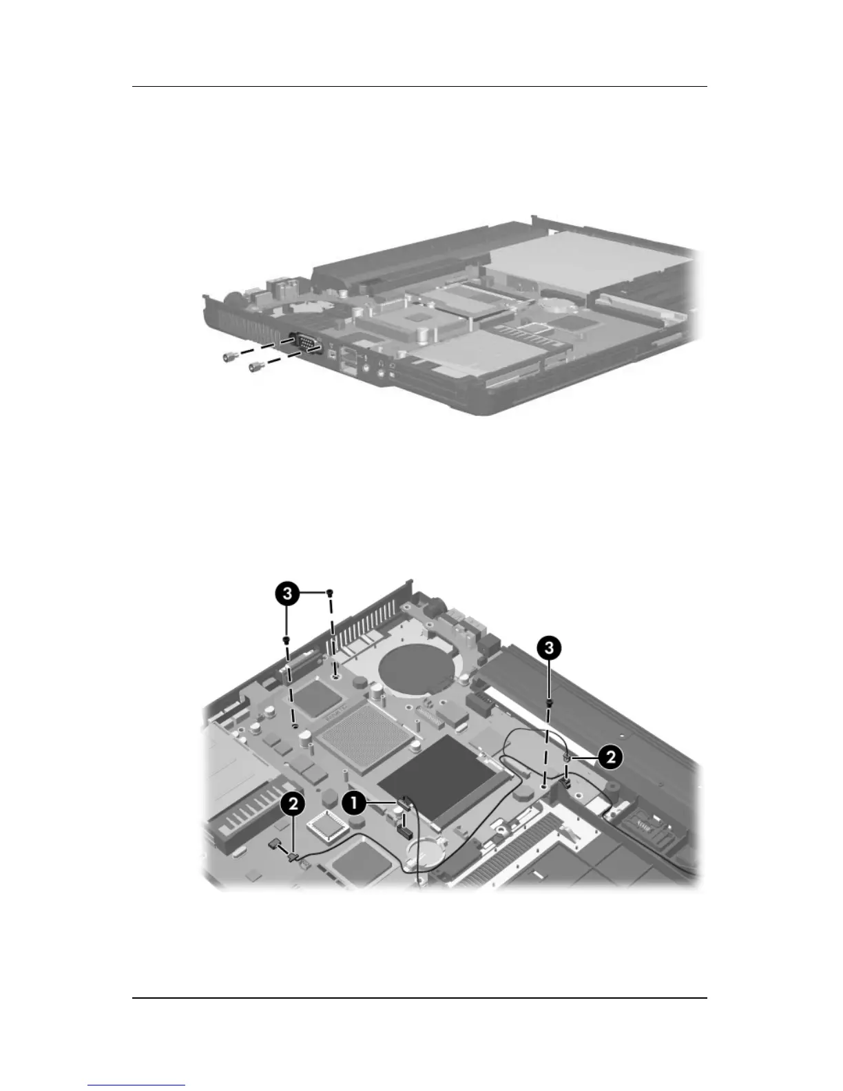
3. Disconnect the Bluetooth cable 1 and RJ-11 connector
module cable 2 from the system board.
4. Remove the 3 Torx T8M2.5×7.0 screws 3 that secure the
system board to the base enclosure.
Removing the System Board Screws and Disconnecting the
System Board Cables
 Loading...