6–52 Maintenance and Service Guide
Removal and Replacement Procedures
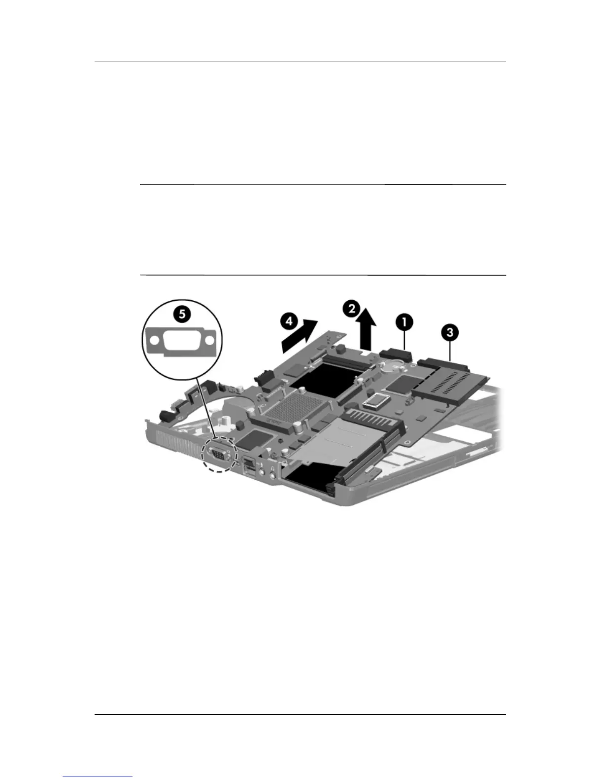
5. Use the optical drive connector 1 to lift the right side of the
system board 2 until the hard drive connector 3 clears the
base enclosure.
6. Slide the system board to the right 4 at an angle and
remove it.
Ä
CAUTION: Be careful not to misplace the external monitor connector
bracket
5 when removing the system board. The bracket should be
installed over the external monitor connector between the base
enclosure and the system board, as shown. Failure to install the external
monitor connector bracket can result in damage to the connector and
system board.
Removing the System Board
 Loading...