8-154
Removal and Installation
HP Designjet 4500 Printer Series Service Manual
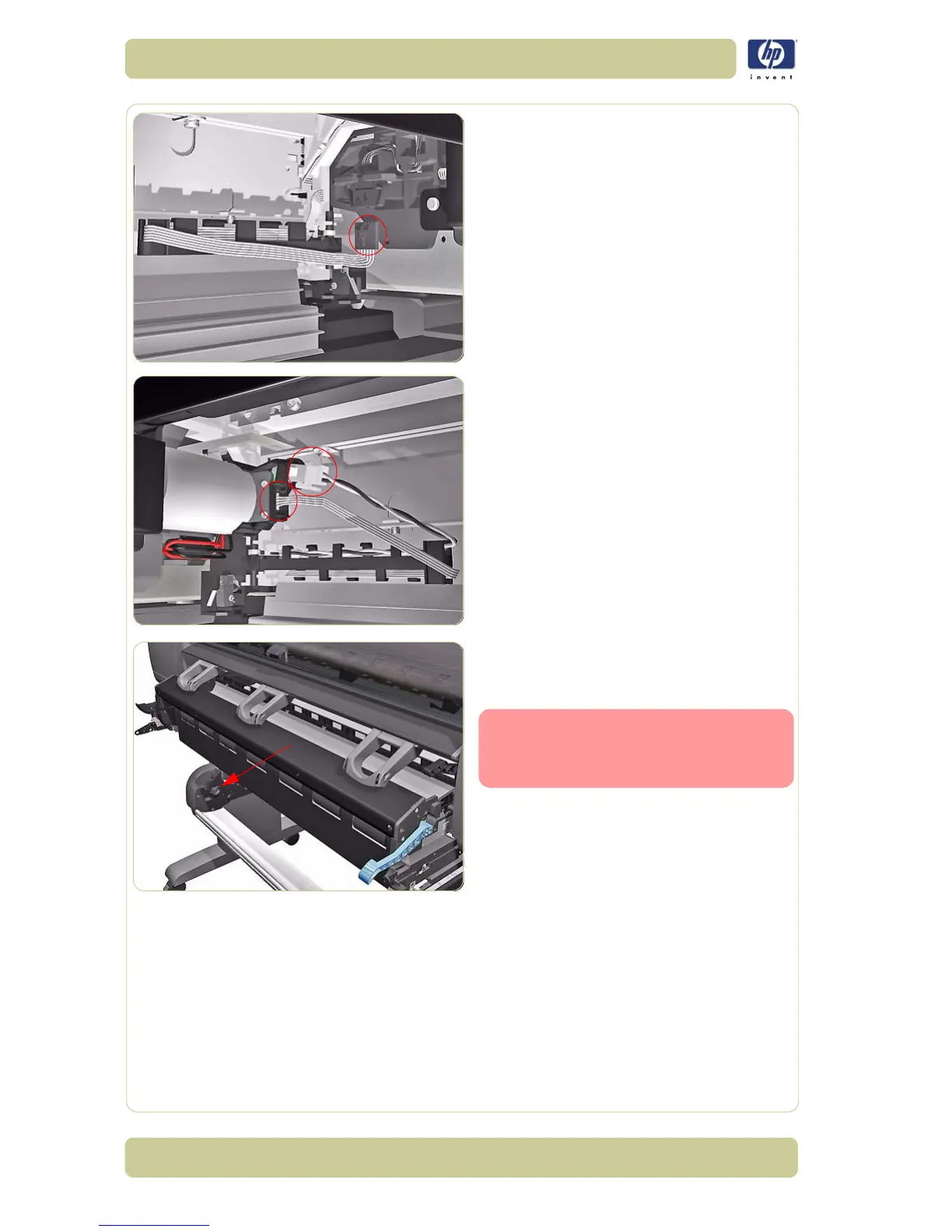
13. Disconnect the Roll 1 Paper Load Lever
Sensor from below the Roll 1 Module on
the right side.
14. Disconnect two cables from the Roll 1 Feed
Motor from below the Roll 1 Module on the
left side.
15. Pull the Roll 1 Module towards you to get
access to the BT Arm located at the rear of
the assembly.
Be careful you do not pull the
whole assembly out at this point
because it will damage the BT
Arm Assembly.
 Loading...

