28 Printer systems
Printer systems
Electronics of the Circuit diagram
The two heating channels (Curing and Dryer) are formed by several heating resistors (R1, R2, etc) and
the corresponding electronics that graduate the amount of energy supplied to these heaters, according to
the orders received from the printer Servo in firmware:
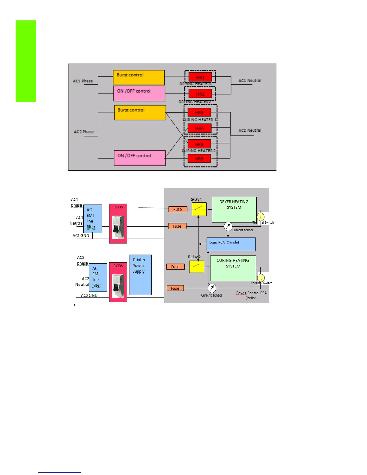
The following diagram summarizes the electronics involved in the heaters control:
The power comes to the heating system via two different power cords, one is supplying energy just to the
Dryer and the other sharing its energy between the Curing heaters and the rest of the printer electronics.
Both AC lines are internally protected by RCDS (Residual Current Sensor), that will trip and cut the AC
power going into the heating system if there is a leakage to Ground above 30mA. This adds extra user
safety as well as avoids potential safety hazards related to the heaters and their control.
Each channel has a Hall current sensor that supplies information to the Logic PCA, and it can decide to
cut the current through the heaters if an over current is detected, controlling the Relay1 and Relay 2,
placed in the Power Control PCA.
Four fuses are placed in the Power Control PCA that supplies a last, but slower, safety protection against
severe electrical problems. These fuses are rated so they will not blow if the heaters are operated at 100%
of power, so if they blow, a severe problem should be suspected in the heater elements or Control
electronics, although big external AC surges could lead to blow fuses.
These fuses are rated 15A, slow blow (HP P/N 2110-1498, LittleFuse 326 015P)
 Loading...