How to Use the Image Quality Service Diagnostic Print 189
Print Quality
a. The top pattern is related to the front printhead (nearest to the user when doing the
pen replacement).
b. The bottom pattern is related to the rear printhead (more far to the user when doing
the pen replacement)
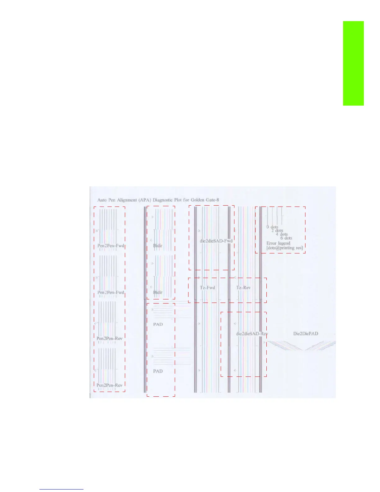
The area to check is the junction (marked with a “-”) of the black with the rest of colors.
4. The alignment in scan axis direction between both printhead of the same color is marked as 4a (in
forward direction die2dieSAD-Fwd) and 4b (in reverser direction die2dieSAD-Rev).
The area to check is the junction (marked with a “-”). The lines have to be continuous.
5. The ThetaZ of the printhead are checked in the area marked as 5. It checks in forward (Tz-Fwd) and
reverse direction (Tz-Rev).
The area to check is the junction (marked with a “-”). The lines have to be continuous.
6. The area marked as number 6 is a reference legend that shows junction misalignments of 2, 4 and
6 dots. The junction to check has to be below 4 in all the cases. If the error we appreciate is above
4 dots, then realign the printheads again.
In the next example, the Bidir is above this 4 dots and the unit should be realigned. The rest of the
pattern shows a right alignment.
 Loading...