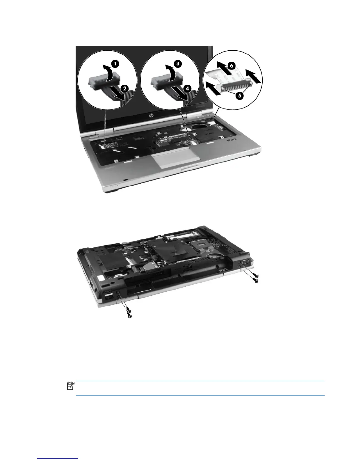
4. Open the ZIF connector for the function board cable (5), and remove the cable (6).
5. Close the display, and position the computer upside down, with the rear toward you.
6. Remove the four Torx 8 2.5x7.0 screws from the hinges.
7. Position the computer with the front toward you. Remove the three Phillips M2.0x7.0 screws (1)
at the front of the computer and the three Phillips M2.0x3.0 screws (2) in the optical drive bay.
8. Remove the three screw covers (3) and the five Torx 8 2.5x7.0 screws (4) along the outside
edges.
9. Remove the three Phillips M2.0x3.0 screws (5) and the two Phillips M1.6 pan-head screws (6)
from the battery bay.
NOTE: Remove the two pan-head screws with a Phillips #0 screwdriver, using a torque of 1.5
kg/cm.
Component replacement procedures 67

 Loading...