EL-MF877-00
Template Revision C
Last revalidation date 09-May-2018
HPI instructions for this template are available at EL-MF877-01
24.
Remove System fan
25.
Remove Front Antenna cable
26.
Remove Rear Antenna cable
27.
Use T-15 screw driver to loose the screws of PSU
28.
Press the PSU’s latch on chassis
29.
Remove the PSU from chassis
30.
Remove four screws covered
31.
Remove the screw and open case
32.
Use PH1 screw driver to remove FG screw
33.
Disconnect fan connector and inlet connector
34.
Loose screws and remove PCB from case
35.
Loose screws and remove PSU fan
36.
Use QUICK 310 to remove Ele-Cap from PCBA
3.2
Optional Graphic. If the disassembly process is complex, insert a graphic illustration below to identify the items
contained in the product that require selective treatment (with descriptions and arrows identifying locations).
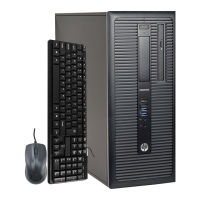
Step1 Use T-15 screwdriver to Loose thumb screw and
remove access panel
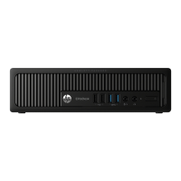
Step2 Disconnect ODD power cable and ODD SATA cable
from ODD
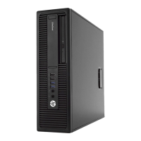
Step3 Press the ODD’s latch on ODD cage
Step4 Remove the ODD from ODD cage
 Loading...