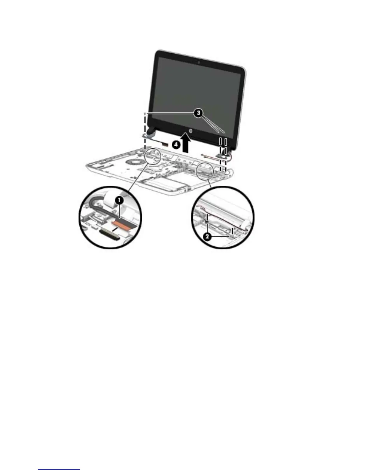
4. Remove the display assembly (4).
If it is necessary to replace any of the display assembly subcomponents:
1. To remove the bezel on non-touch screen models:
The display bezel for non-touch models is available using spare part number 767365-001.
a. Remove the plastic screw covers (1) and the two Phillips M2.5×3.0 screws (2) that secure
the display bezel to the display assembly.
b. Flex the inside edges of the top edge (3), the left and right sides (4), and the bottom edge (5) of
the display bezel until the bezel disengages from the display enclosure.
Component replacement procedures 67

 Loading...