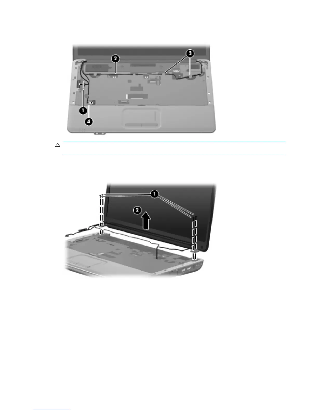
3. Disconnect the webcam module cable (4) from the system board.
CAUTION: The display assembly will be unsupported when the following screws are removed.
To prevent damage to the display assembly, support it before removing the screws.
4. Remove the four Phillips PM2.5×10.0 screws (1) that secure the display assembly to the computer.
5. Lift the display assembly (2) straight up and remove it.
58 Chapter 4 Removal and replacement procedures