Do you have a question about the HP HP417 and is the answer not in the manual?
This document provides comprehensive instructions for the disassembly of the HP417 Unified Wired-WLAN Appliance, specifically models JG971A_9801A0NA, JG972A_9801A0NB, JG973A_9801A0NC, and JG974A_9801A0ND. These instructions are primarily intended for end-of-life recyclers and treatment facilities, ensuring compliance with the EU directive 2002/96/EC on Waste Electrical and Electronic Equipment (WEEE) by facilitating the removal of components and materials requiring selective treatment.
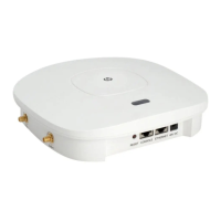
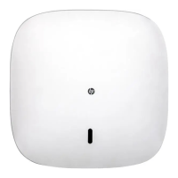
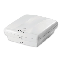
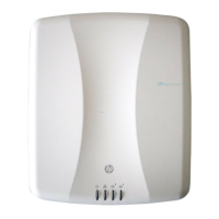
The HP417 Unified Wired-WLAN Appliance is categorized as networking equipment, designed to provide integrated wired and wireless connectivity solutions. Its primary function is to serve as a central hub for network management and data transmission, supporting both wired Ethernet connections and wireless local area network (WLAN) capabilities. This appliance is engineered to deliver reliable and efficient network performance in various environments, from small offices to larger enterprise settings. The unified nature of the device means it can seamlessly integrate and manage both types of network traffic, simplifying network infrastructure and reducing the need for separate devices for wired and wireless access.
From a usage perspective, the HP417 appliance is designed for straightforward deployment and operation within existing network infrastructures. It is typically mounted in a rack or cabinet, allowing for organized and secure installation alongside other networking hardware. The device's robust construction ensures durability and consistent performance over its operational lifespan. While the document focuses on end-of-life procedures, the design implies features that support ease of installation and integration into diverse network setups. The appliance's ability to handle both wired and wireless functionalities makes it a versatile solution for organizations looking to streamline their network architecture and provide flexible access options for users. Its role as a TAA (Trade Agreements Act) compliant appliance further indicates its suitability for government and public sector procurements, where specific sourcing requirements must be met.
Regarding maintenance and end-of-life considerations, the document meticulously outlines the steps for selective treatment, which is crucial for environmental responsibility. The disassembly process is designed to be systematic, ensuring that hazardous materials and valuable components are properly segregated for recycling or safe disposal. The primary tools required for this process include a screwdriver, specifically a #1 size, indicating that standard tools are sufficient for the initial stages of disassembly. This simplifies the process for recyclers, as no specialized or proprietary tools are needed for basic component removal.
The selective treatment items identified in the document include Printed Circuit Boards (PCBs) or Printed Circuit Assemblies (PCAs) with a surface area greater than 10 sq cm. The HP417 appliance contains two such boards: a Main Board and a Daughter Board. These components are critical for the device's functionality and often contain materials that require special handling, such as heavy metals and flame retardants. The document also lists various screws and nuts that need to be removed during disassembly, including self-tapping screws (P27mm), standoffs (M2(10.05+5.00)mm), machine screws (P26.5mm), and nuts (M24*1.6mm). The detailed specification of these fasteners, including their dimensions and plating (e.g., nickel plating by Changhui for screws and standoffs), helps recyclers identify and manage these small but numerous components.
The disassembly process begins with the removal of the mounting angle, which secures the appliance to a rack or cabinet. This step involves unscrewing the fasteners that hold the mounting angle in place. Following this, the top and bottom housing of the HP417 appliance are separated by removing four self-tapping screws. Further disassembly involves detaching the Daughter PCBA from the bottom housing by removing two self-tapping screws and two machine screws. The Main PCBA is then accessed by unscrewing two M2 standoffs and two M2*4 nuts. These steps systematically expose the internal components, allowing for the removal of the PCBs and other selectively treated materials.
The document also includes optional graphic illustrations to aid recyclers in identifying the items and their locations within the product, particularly for complex disassembly processes. Figure 1 illustrates the removal of the mounting angle, showing the screw locations. Figure 2 depicts the separation of the bottom cover, providing a visual guide for accessing the internal components. Figure 3 details the treatments to the standoffs and PCBs, showing how these components are secured and subsequently removed. These visual aids are invaluable for ensuring that recyclers can efficiently and correctly perform the selective treatment procedures.
Finally, the document emphasizes the importance of clearing any "black glue" (黑膠) and adhesive tape from the PCBA and housing, if present. This step is crucial for ensuring that all materials are properly separated and prepared for recycling or disposal, as adhesives can sometimes interfere with material recovery processes. The revision record indicates that the document was initially created on October 27, 2014, by Bo.Chen/Eddie, signifying a structured approach to documentation and version control. This detailed guide underscores HP's commitment to environmental responsibility throughout the product lifecycle, from design to end-of-life management.
| Product Name | HP HP417 |
|---|---|
| Maximum Data Rate | 1200 Mbps |
| Wi-Fi Bands | Dual Band |
| Wireless Standard | 802.11ac |
| Wireless Standards | 802.11a/b/g/n/ac |
| Frequency Band | 2.4 GHz / 5 GHz |
| Antenna | Internal antenna |
| Ethernet Ports | 1 x 10/100/1000 Mbps Gigabit Ethernet port |
| Security Features | WPA, WPA2, WPA3 |
| Power Supply | 12V DC |
| Operating Temperature | 0°C to 40°C (32°F to 104°F) |