2-12
Installing the Switch
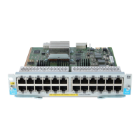
Installation Procedure
Wall anchors are included in the accessory kit for use with plastered brick
or concrete walls.
3. For under-table mounting, a third 20-mm M4 tap screw can be placed
against one side of the switch to secure it in place.
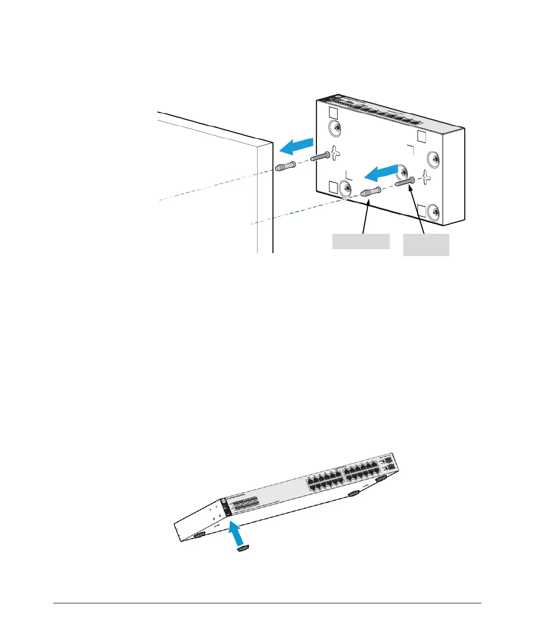
Horizontal Surface Mounting
Place the switch on a table or other horizontal surface. The switch comes with
rubber feet in the accessory kit that can be used to help keep the switch from
sliding on the surface.
Attach the rubber feet to the four corners on the bottom of the switch within
the embossed angled lines. Use a sturdy surface in an uncluttered area. You
may want to secure the networking cables and switch power cord to the table
leg or other part of the surface structure to help prevent tripping over the
cords.
20-mm M4
tap screws
Wall anchors

 Loading...