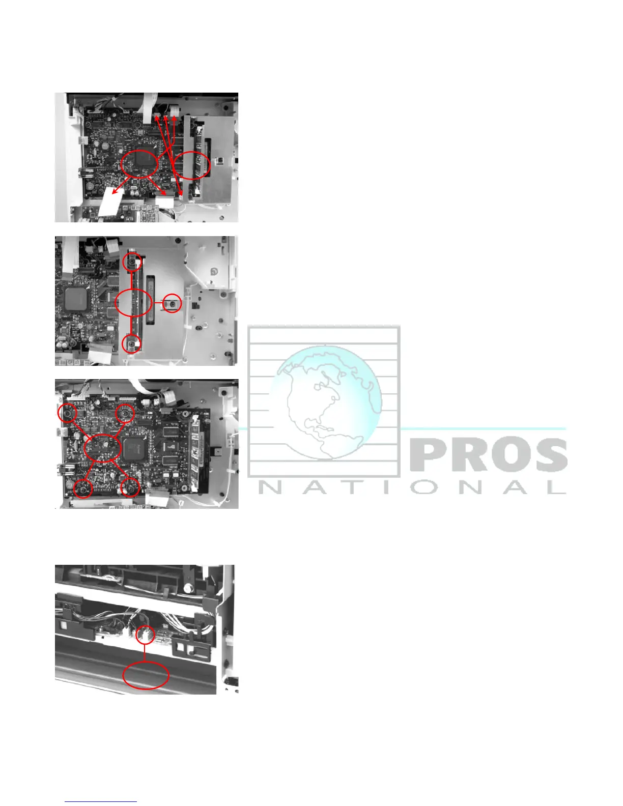
9. Remove Formatter
a.) Disconnect three wire connecters (callout 21; P13,P14,P15) and three ribbon cables (callout 22;
J7,J10,J11)
b.) Remove three screws form metal cover (callout 23) then remove metal cover
c.) Remove four screws from formatter (callout 24), Then remove formatter from printer
10. Remove Fan
a.) Disconnect one connector (callout 25) from the ECU and feed the wire harness through the hole in the
chassis (the hole is behind the power switch PCA. It is easier to feed the wire with the power switch PCA
removed but not necessary)
 Loading...