Paper-pickup assembly
1. Remove the following assemblies:
●
Scanner assembly. See
Scanner assembly on page 85.
●
Left cover. See
Side covers on page 110.
●
Rear cover and fuser cover. See
Rear cover and fuser cover on page 113.
●
Print-cartridge door. See
Print-cartridge door on page 112.
●
Front cover. See
Front cover on page 115.
●
Transfer roller. See
Transfer roller on page 108.
●
Fuser. See
Fuser on page 134.
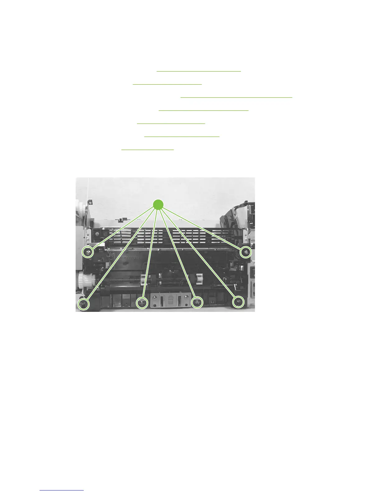
2. Remove six screws (callout 1).
Figure 6-101 Removing the paper-pickup assembly
1
3. Unplug and remove any additional wire-harnesses as necessary to release the paper-pickup
assembly. Unplug and remove the wire from the solenoid to the formatter.
4. Lift the assembly out of the frame.
136 Chapter 6 Removal and replacement ENWW
 Loading...
