Fuser-motor assembly
Before proceeding, remove the following components:
●
Right cover. See Right cover on page 25.
●
Control panel and right-arm mount. See Control panel and right-arm mount on page 39.
●
Formatter and fax PCAs. See Formatter PCA on page 65.
●
Rear-upper cover. See Rear-upper cover on page 28.
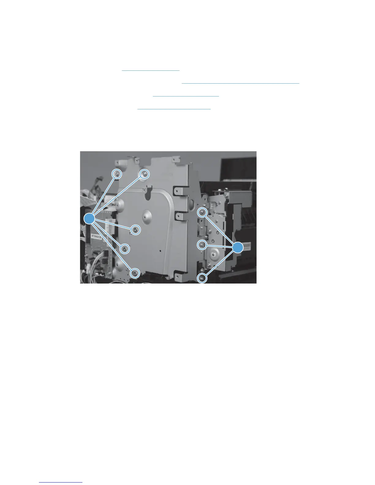
Remove the fuser-motor assembly
1. Remove 5 screws (callout 1) and 3 screws (callout 2).
Figure 1-93 Remove the fuser-motor assembly (1 of 6)
 Loading...