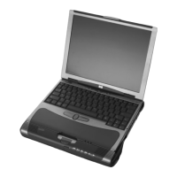
3. Remove the 4 Torx T8 2.5×5.0 screws (1), and the 4 Phillips PM2.0×3.0 screws (2) that secure
the top cover to the base enclosure.
4. Turn the device right-side up, with the front toward you.
5. Open the device as far as possible.
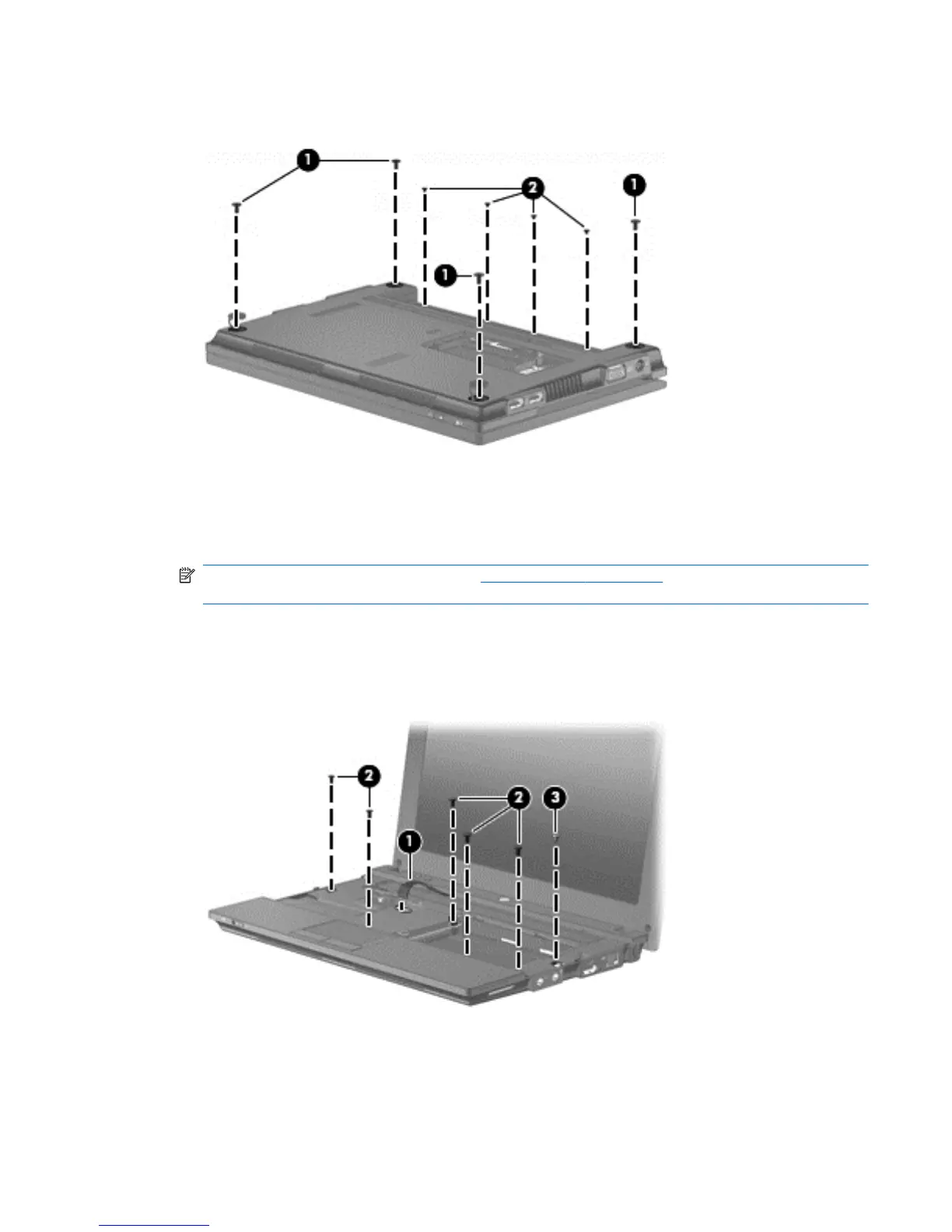
6. Release the ZIF connector (1) that connects the button board cable to the system board.
NOTE: If not done when removing the WLAN module on page 53, release any WLAN cable
routed along the top cover.
7. Remove the following screws that secure the top cover to the base enclosure:
●
(2) - 5 Phillips PM2.0×6.0
●
(3) - 1 Phillips PM2.0×2.5
8. Release the clips along the front edge of the top cover and open the front of the top cover (1)
enough to see the TouchPad and speaker cables.
Component replacement procedures 57
 Loading...