2. Disconnect the fan cable from the system board.
3. Turn the system board right side up.
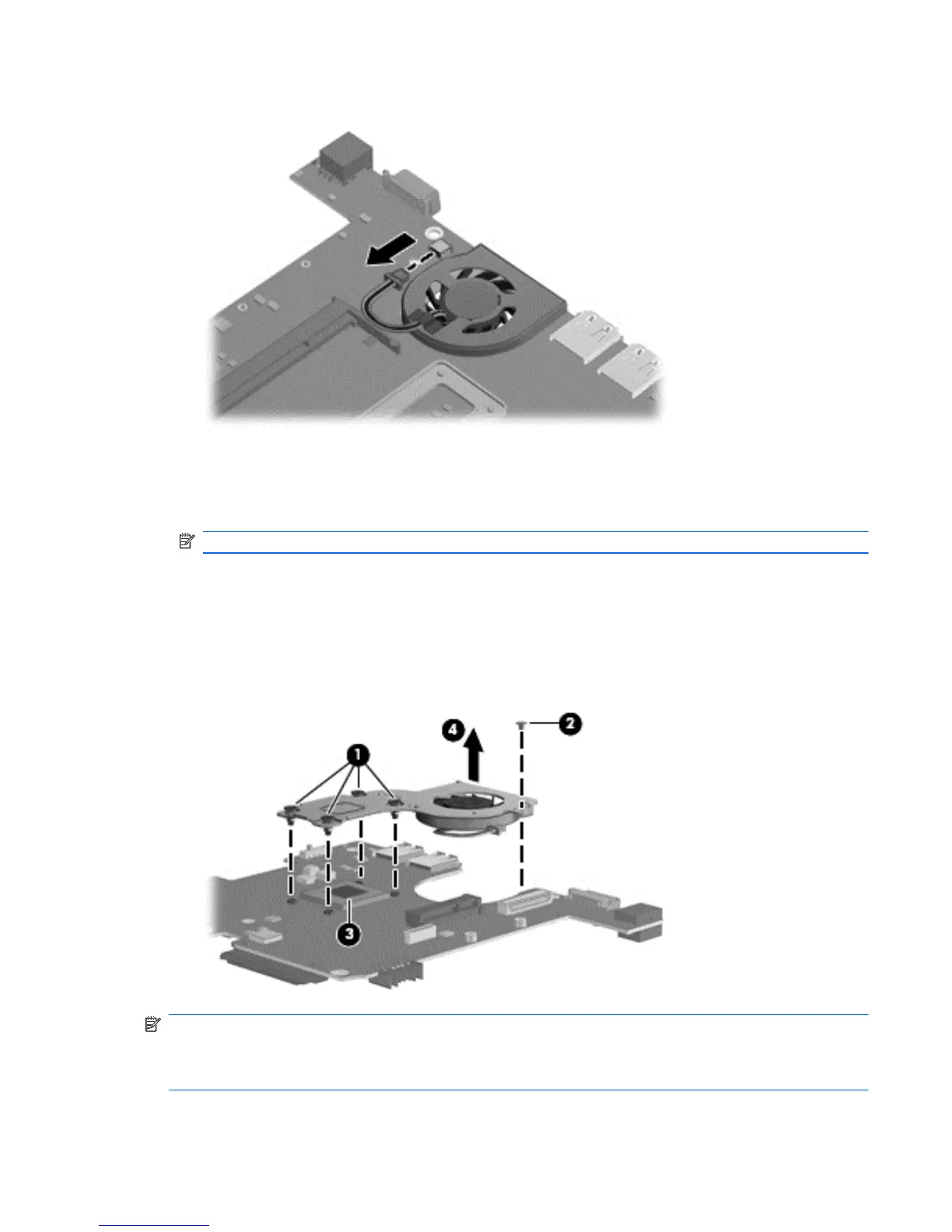
4. Loosen the 4 Phillips PM2.5×5.0 captive screws (1) that secure the fan and heat sink assembly
to the system board.
NOTE: The screws are numbered 1 through 4. Follow this order when removing the screws.
5. Remove the Phillips PM2.0×3.0 screw (2) that secures the fan and heat sink assembly to the
system board.
6. If necessary, work the heat sink back and forth to release the heat sink from the thermal paste
(3) on the processor.
7. Remove the fan and heat sink assembly (4).
NOTE: The thermal material must be thoroughly cleaned from the surfaces of the fan and heat sink
assembly and the system board each time the fan and heat sink assembly is removed. Thermal paste
is used on the processor (1). Replacement thermal material is included with all fan and heat sink
assembly, and system board spare part kits.
Component replacement procedures 77

 Loading...