7.
Remove the WLAN module compartment cover and disconnect the wireless antenna cables from the
WLAN module (see
WLAN module on page 44).
8.
Remove the following components:.
a.
Keyboard (see
Keyboard on page 47)
b.
Switch cover (see
Switch cover on page 50)
Remove the display assembly:
1.
Close the computer and turn it upside down, with the front toward you.
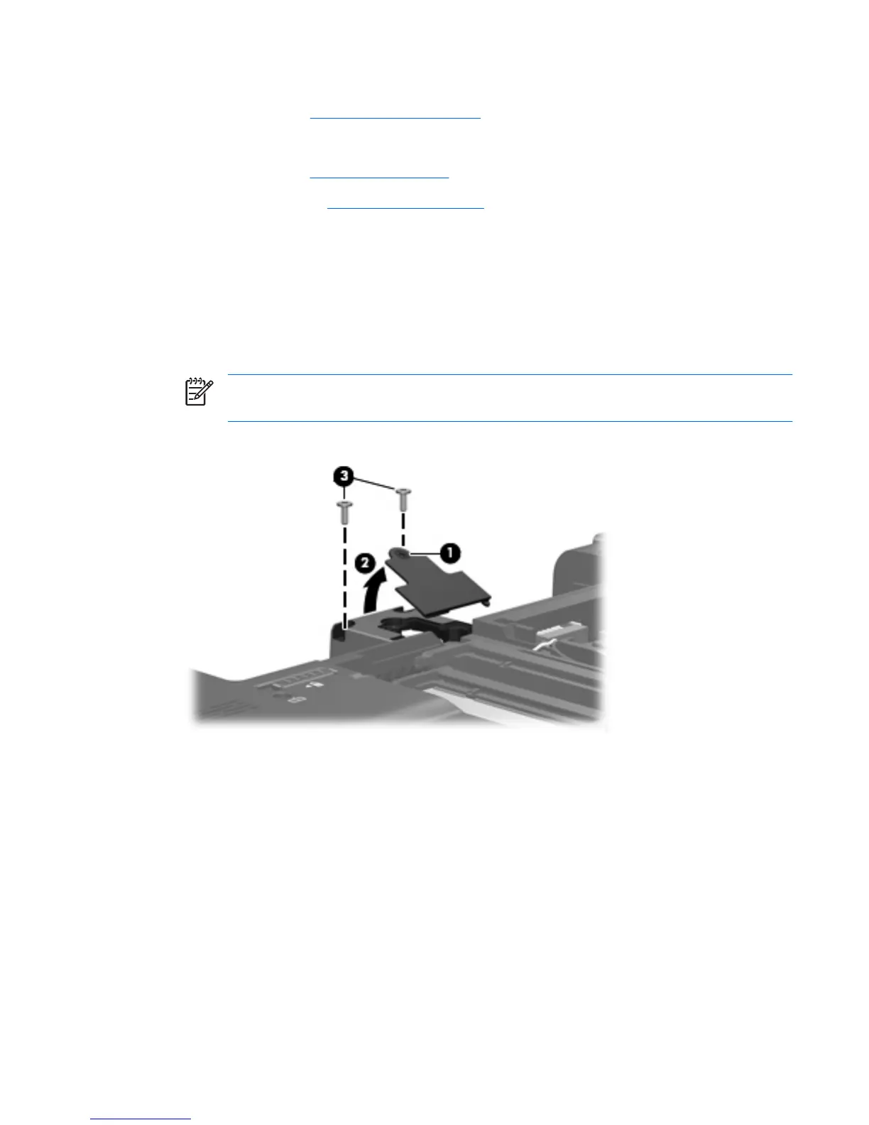
2. Loosen the Phillips PM2.0×4.0 screw (1) that secures the display connector cover to the computer.
3. Lift the rear edge of the display connector cover (2) and swing it toward you.
4.
Remove the display connector cover.
NOTE: The display connector cover is included in the Plastics Kit, spare part number
441138-001.
5. Remove the two Phillips PM2.5×6.0 screws (3) that secure the display assembly to the computer.
6. Remove the WWAN antenna cable (1) from the routing channel built into the base enclosure.
ENWW Component replacement procedures 53
 Loading...