6. Push in on the lever to the left of the assembly.
Figure 7-19 Front I/O connectors
7. Pull the assembly outward away from the front of the chassis while guiding the cables through
the hole in the chassis.
To install the housing assembly, reverse the removal procedures.
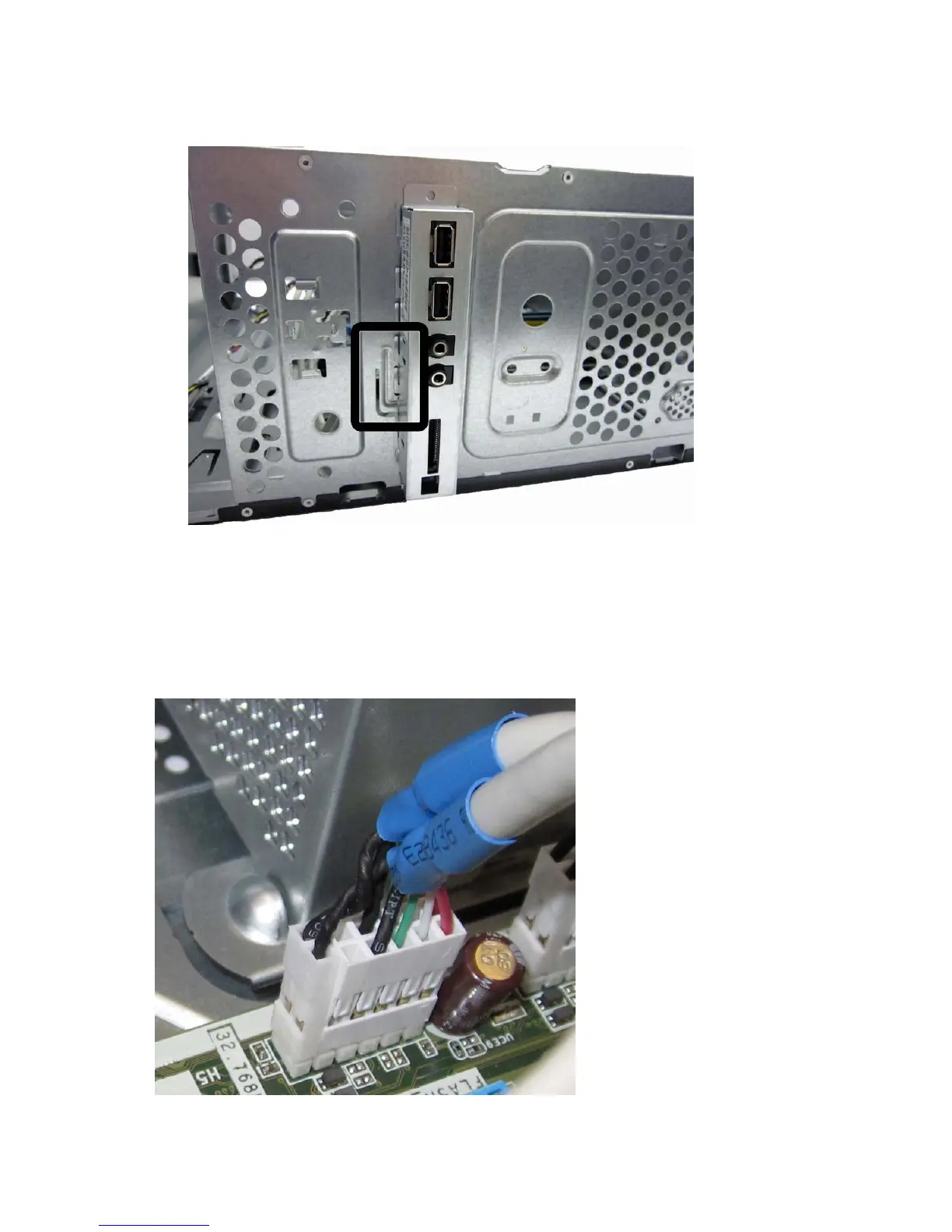
When installing the assembly, note that some cables have two separate connectors that plug into the
same system board.
Figure 7-20 Front I/O connectors
66 Chapter 7 Removal and Replacement Procedures – Microtower Chassis