Removal and replacement procedures 40
2.
Install the PCIe riser cage ("PCIe riser cage (primary)" on page 31).
3. Install the access panel ("Access panel" on page 29).
4. Slide the server into the rack.
5. Connect the LAN segment cables.
6. Connect each power cord to the server.
7. Connect each power cord to the power source.
8. Power up the server.
Front panel assembly
WARNING: To reduce the risk of personal injury, electric shock, or damage to the equipment,
remove the power cord to remove power from the server. The front panel Power On/Standby
button does not completely shut off system power. Portions of the power supply and some internal
circuitry remain active until AC power is removed.
To remove the component:
1. Power down the server (on page 25).
2. Remove all power:
a. Disconnect each power cord from the power source.
b. Disconnect each power cord from the server.
3. Extend the server from the rack (on page 25).
4. Remove the access panel ("Access panel" on page 29).
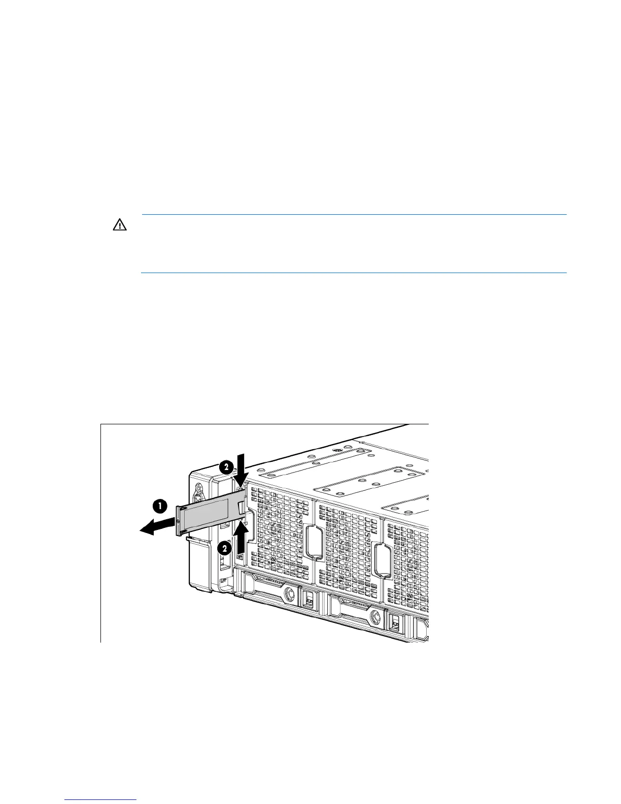
5. Remove the serial label pull tab and retain it for the new front panel assembly.
6. Remove the air baffle ("Air baffle" on page 29).
7. Remove all fan modules ("Hot-plug fan" on page 37).
8. Remove all drives ("Hot-plug drive" on page 34).
9. Disconnect all cables from the front panel assembly.
 Loading...