46
Rear panel LED indicators
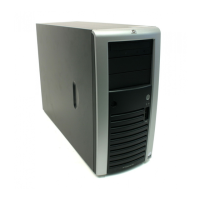
The LAN port on the rear panel has two LED indicators that allow monitoring of network activity. Figure -7 and
Table -4 show and describe the function of these LEDs.
Figure -7 [LAN/LED indicators]
Table -4 LAN/LED indicator states
Item Component Status Description
Flashing green Ongoing network data activity. 1 LAN activity status LED indicator
Off No network data activity or no connection.
Steady green The LAN connection is using a GbE link.
Steady amber The LAN connection is using a 100 Mbps link.
2 LAN network speed LED indicator
Off The LAN connection is using a 10 Mbps link or no connection.
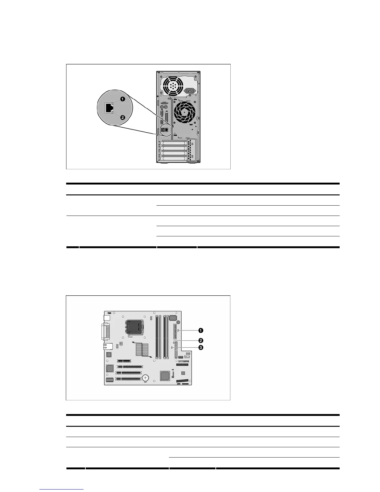
System board LED indicators
The system board contains two internal power status LED indicators for use during troubleshooting operations.
Figure -8 and Table -5 show and describe the function of these LEDs.
Figure -8 [System board LED indicators]
Table -5 System board LED indicators
Item Component Status Description
1 5V aux power indicator (CR1) Green Auxiliary power present
2 3.3V aux power indicator (CR2) Off The server is powered off (AC power disconnected).
Red A system error has occurred. 3 System Error Indicator (CR7)
Off System is operating under normal condition.
 Loading...