Component identification 11
* For more information on the expansion slot specifications, see "PCIe expansion slot definitions."
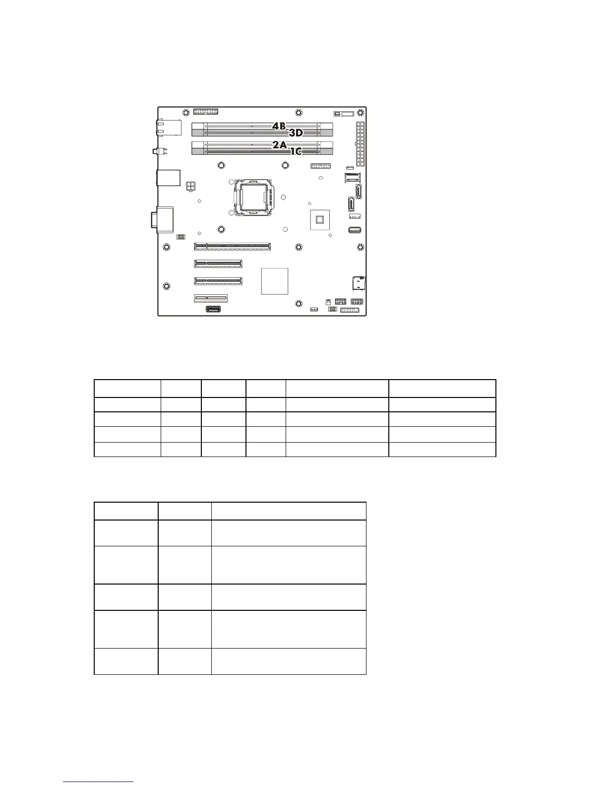
DIMM slot locations
DIMM slots are numbered 1 through 4. Letters are used for AMP mode DIMM ordering.
PCIe expansion slot definitions
Slot number Type Length Height Connector link width Negotiable link width
1
PCIe2 Half Full x4 x1
2
PCIe2 Full Full x8 x1
3
PCIe3 Full Full x8 x8
4
PCIe3 Full Full x16 x8
System maintenance switch
Switch Default Function
1
Off Off = No function
On = iLO security is disabled
2
Off Off = System configuration can be
changed
On = System configuration is locked
5
Off Off = Power-on password is enabled
On = Power-on password is disabled
6
Off Off = No function
On = ROM reads configuration as
invalid
3, 4, 7, 8, 9,
10, 11, 12
— Reserved
When the system maintenance switch position 6 is set to the On position, the system is prepared to erase all
system configuration settings from both CMOS and NVRAM.
 Loading...