EasyManua.ls Logo

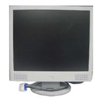
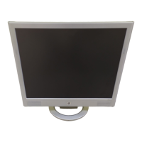
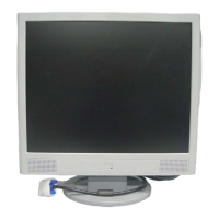
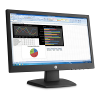
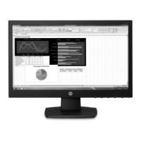
HP VS17E User Manual

HP VS17E
58 pages
To Next Page IconTo Next Page
Page #1 background imageLoading...
Page #1 background image
HP VS17E
1
SERVICE MANUAL
17” LCD Monitor
VS17E
THESE DOCUMENTS ARE FOR REPAIR SERVICE INFORMATION ONLY. EVERY REASONABLE
EFFORT HAS BEEN MADE TO ENSURE THE ACCURACY OF THIS MANUAL; WE CANNOT GUARANTEE THE
ACCURACY OF THIS INFORMATION AFTER THE DATE OF PUBLICATION AND DISCLAIMS RELIABILITY FOR
CHANGES, ERRORS OR OMISSIONS.

Questions and Answers:

HP VS17E Specifications

General IconGeneral
Screen Size17 inches
Resolution1280 x 1024
Panel TypeTN
Aspect Ratio5:4
Brightness250 cd/m²
Response Time5 ms
ConnectivityVGA
Viewing Angle160° horizontal, 160° vertical

Summary

Revision List

Monitor Specifications

LCD Panel Specifications

Details about the LCD panel, size, pixel pitch, brightness, and viewable angle.

Input and Power Requirements

Input signal types, power consumption, and power source specifications.

Monitor Overview

LCD Monitor Description

Overview of monitor components like main board, power board, and key board.

Operation Instructions

Guide on turning the monitor on/off and using control buttons.

Control Button Functions

Detailed explanation of each control button's function and indicator lights.

Picture Adjustment

Main Menu Controls

Lists all adjustable picture settings and their corresponding controls in the OSD.

Input/Output Specifications

Input Signal Connector Details

Pinout and signal assignments for the VGA input connector.

Factory Preset Display Modes

Table of resolutions, frequencies, and polarities for preset display modes.

Power Supply Requirements

AC input voltage, frequency, inrush, leakage, and power consumption limits.

Panel Specifications

General Panel Features

Display area, pixel arrangement, colors, and surface treatment details.

Mechanical Panel Dimensions

Physical dimensions (H, V, D) and weight of the LCD panel module.

Optical Characteristics

Contrast ratio, response time, luminance, and viewing angle specifications.

Block Diagrams

Monitor Exploded View

Visual breakdown of the monitor's physical components and assembly.

Software Flow Chart

Diagram illustrating the monitor's software operational logic and decision points.

Electrical Block Diagrams

Block diagrams for the Scalar, Inverter, and Power boards.

Schematics

Main Board Schematic

Detailed circuit diagram for the monitor's main processing board.

Power Board Schematic

Circuit diagram for the power supply and inverter board.

PCB Layouts

Main Board PCB Layout

Physical component placement and routing for the main board.

Inverter/Power Board PCB Layout

Component layout for the inverter and power supply board.

Key Board PCB Layout

Component layout for the user input key board.

Maintainability and Troubleshooting

Required Tools and Equipment

List of necessary tools for maintenance and repair.

Troubleshooting Procedures

Diagnostic flowcharts for common issues like no power, no picture, and keypad problems.

Calibration and Adjustment Procedures

White-Balance and Luminance Adjustment

Procedure for adjusting color temperature and brightness using calibration tools.

DDC Writing and EDID Management

Steps for writing DDC information and checking EDID data.

EDID Content

Bill of Materials (BOM)

Related product manuals