Do you have a question about the HPE Aruba 6200F and is the answer not in the manual?
PCB/PCA components requiring selective treatment.
All types of batteries require specific handling.
Components containing mercury, such as lamps, need careful removal.
LCD screens over 100 sq cm may require specific disassembly.
CRT displays require specialized handling due to hazardous materials.
Capacitors over 2.5 cm need selective treatment.
Standard cables usually do not require special treatment.
Lamps, especially illuminated displays, may contain hazardous substances.
Plastics with BFRs weighing > 25g need separate handling.
Ink and toner cartridges need specific disposal procedures.
Asbestos-containing materials are hazardous and require strict handling.
Specific torque drivers and bits (T10, T25, M4 Philip) are needed for disassembly.
Tools like cutters and soldering stations may be required for component removal.
Steps 1-10 cover initial parts removal like covers, screws, and cables.
Steps 11-26 detail removing the power supply, PCBA, and related components.
Steps 27-30 cover the final removal of chassis parts and specific components.
This document outlines the disassembly procedures for Hewlett Packard Enterprise (HPE) networking products, specifically focusing on models JL725A and JL727A from the Aruba 6200F series. These instructions are primarily intended for end-of-life recyclers and treatment facilities, ensuring proper handling and removal of components requiring selective treatment as mandated by Directive 2012/19/EU (WEEE). The core function of this document is to facilitate environmentally responsible disposal and recycling by providing a clear, step-by-step guide for dismantling the device.
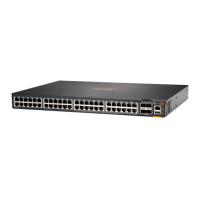
The device itself is a network switch, designed to manage and direct data traffic within a network. Its primary function is to connect multiple devices on a computer network, such as computers, servers, and other network peripherals, allowing them to communicate efficiently. The Aruba 6200F series switches are typically deployed in enterprise environments, offering robust connectivity and performance for various networking needs. These switches are integral to building scalable and reliable network infrastructures, supporting a range of applications and services.
From a usage perspective, these networking switches are designed for continuous operation within controlled environments, such as data centers or server rooms. They are typically rack-mounted, integrating seamlessly into existing network infrastructure. The design emphasizes reliability and performance, crucial for maintaining network uptime and data flow. While the document focuses on end-of-life processes, it implicitly highlights the device's robust construction, which is necessary for its operational lifespan. The presence of multiple ports (24G or 48G, plus SFP+ uplinks) indicates its capacity to handle a significant number of network connections, catering to medium to large-scale network deployments. The inclusion of a power supply (370W) further underscores its capability to support demanding network operations.
Maintenance features, as implied by the disassembly instructions, are geared towards component replacement and end-of-life processing rather than routine user maintenance. The detailed steps for removing various components, such as printed circuit boards (PCBs), power supplies, fans, and cables, suggest a modular design that facilitates repair and component-level servicing. For instance, the instructions for unplugging and unscrewing specific components indicate that internal parts can be accessed and replaced if necessary, extending the device's operational life. The emphasis on selective treatment for items like PCBs, batteries, and capacitors also points to the environmental considerations embedded in the product's lifecycle management. While users typically interact with the device through its network management interface for configuration and monitoring, the physical maintenance, as detailed here, is performed by trained technicians.
The disassembly process itself is meticulously detailed, starting with the removal of external covers and progressing to internal components. Tools required for this process include torque drivers with specific bits (T10, T25, M4 Philip Head) and a cutter, indicating the need for specialized equipment for safe and efficient dismantling. The instructions cover the removal of various cables (AC, power supply, fan, FFC), connectors, and screws, highlighting the intricate internal structure of the device. The inclusion of graphics with numbered labels further aids in identifying specific components and their locations, making the process intuitive for recyclers. For example, the identification of the main board, LED board, and power supply unit (PSU) is crucial for targeted removal of selective treatment items.
Key components requiring selective treatment include printed circuit boards (PCBs) or printed circuit assemblies (PCAs) with a surface greater than 10 sq cm, and batteries (all types, including standard alkaline and lithium coin/button style). The document also mentions mercury-containing components, liquid crystal displays (LCDs) with a surface greater than 100 sq cm, cathode ray tubes (CRTs), capacitors/condensers (especially those containing PCB/PCT or measuring greater than 2.5 cm in diameter/height), external electrical cables and cords, gas discharge lamps, plastics containing brominated flame retardants (weighing > 25 grams), and components containing toner/ink or asbestos. This comprehensive list ensures that all potentially hazardous or valuable materials are identified and handled appropriately during the recycling process.
The step-by-step instructions, such as "Unscrew and remove - M5 SCREW at 1 Location" or "Unplug - AC connector from POWER SUPPLY," provide a clear sequence for dismantling. The process moves from external access to internal component removal, ensuring that the device can be systematically taken apart. The final steps involve desoldering capacitors from the PSU PCBA and removing the saddle cable from the shield PSU cable, indicating that some parts require more advanced techniques for removal. This level of detail is essential for compliance with WEEE directives, which aim to minimize the environmental impact of electronic waste by promoting recovery and recycling of materials.
In summary, this document serves as a critical guide for the end-of-life management of HPE Aruba 6200F series networking switches. It underscores the device's robust design, its function as a core networking component, and the detailed procedures for its environmentally responsible disassembly and recycling.
| Model | HPE Aruba 6200F |
|---|---|
| Operating Temperature | 0°C to 45°C (32°F to 113°F) |
| Power Supply | Internal |
| Layer | Layer 3 |
| Management | Aruba Central, CLI, Web GUI, SNMP |
| PoE | Optional PoE+ or PoE++ support |
| Input Voltage | 100-240 VAC |
| Stacking | Up to 8 units |
| Jumbo Frames | Up to 9, 216 bytes |
| Memory | 4 GB |
| Ports | 24x 1GbE |
| Memory and Processor | Dual Core ARM Cortex A9 @ 1016MHz |
| Latency | < 2.3 µs |