Installation instructions
Whenselectingtheinstallationlocation,observethefollowing
instructions:
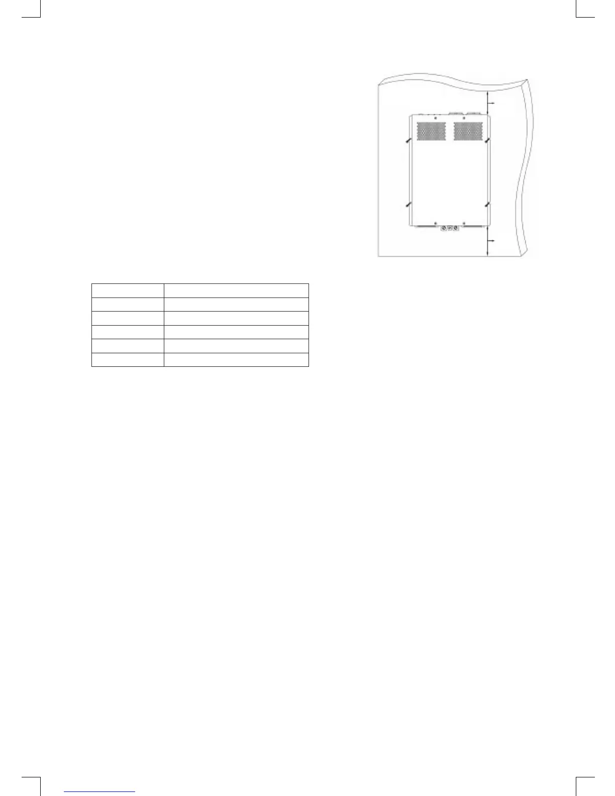
• Installationoftheinvertercanbedonehorizontallyor
vertically.
• Theinverterhastobeinstalledinadryandcleanplacethatis
notexposedtohumidity.
• Makesurethattheplaceiswellventilated.Ifinstalledinto
housing,ensureproperventilation.Keepafreespaceofat
least 10 cm around the inverter.
• Theairintakeatthebottomoftheinverterandtheairoutletat
the back should not be blocked.
• Theinstallationsurfacemustbelevelandofsufcient
strength.
Incasetheinverterisinstalledintovehiclesorboatsithastobe
connected to the chassis (ground).
Observetherequiredcablecrosssection(seetable).
10cm
10cm
Device Minimum cable thickness
150W 2.5 mm
2
300W 6.0 mm
2
600W 10.0 mm
2
1000W 35.0 mm
2
2000W 50.0 mm
2
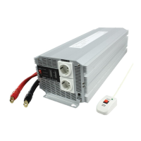
1. Laytheexibleconnectingcable(plusandminus)fromthebatterytotheconnectingpolesofthe
inverter.
Warning!
Makesurethatthepolesarenotbeingexchanged!Reversedpolaritywillblowtheinternalfuses.
Exchangeoffusesshouldbedonebyexpertsonly!
2. Connect the cable and the terminal together.
3. First connect the negative cable to the white negative terminal.
4. InstallaDCfuseoraDCcircuitbreakeratthepositivesideofthecircuitwithin18inchesofthe
battery.
5. Connect the positive cable to the red positive terminal.
Warning!
Inorderfortheintegratedresidualcurrent-operatedprotectivedeviceoftheinverterstowork
properly,theearthconnectionoftheinvertermustbeelectricallyconnectedtothechassisofthe
vehicle or boat.
6. Laytheexibleearthcablefromtheearthpointofthevehicletotheearthpointoftheinverter.
7. Connect the earth cable to the chassis terminal.
Warning!
Reversed polarity of the battery wires can damage the inverter. Do not use the inverter with
electrical systems using positive ground.
Using the inverter
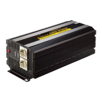
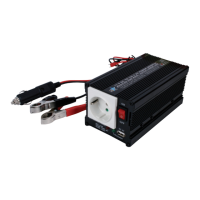
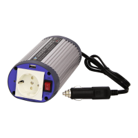
120/150/300/600 W models:
Never connect more than one consumer unit to the 230 V socket on the front of the device.
>600 W models:
Never connect more than two consumer units to each of the 230 V sockets on the front of the device.
 Loading...