−
4
−
2-5. 圧着部の引っ張り強度及び測定方法 /
Tensile strength of crimped section and measuring method
2-5-1. 圧着部引っ張り強度 /圧着部引っ張り強度 //
Tensile strength of crimped section
芯線圧着部(ワイヤーバレル部)の電線を引っ張った時に耐えられる強さのことで、端子ごと、電線ごとに許容値
を設定しています。
Retention strength of the crimped wire when the pull force (N) is applied to it. The pull force is dened for each style of the con-
tact.
2-5-2. 引っ張り強度の試験方法 /引っ張り強度の試験方法 /
Testing method of tensile strength
インシュレーションバレルが機能しないように、電線を長めにストラップしたものを圧着し、引っ張り試験機に取
りつけ、電線が破断した時の値を測定します。(電線の引っ張り速度は 20mm ~ 80mm/ 分に設定してください。)
Secure the crimped contact on applicable xture assuring that the wire can be freely pulled and the force can be measured.
Apply pull at the rate of 20 to 80 mm per minute until the failure of the crimp section (wire pulled-out). The value of the pull-out
force must be higher than the minimum specied.
2
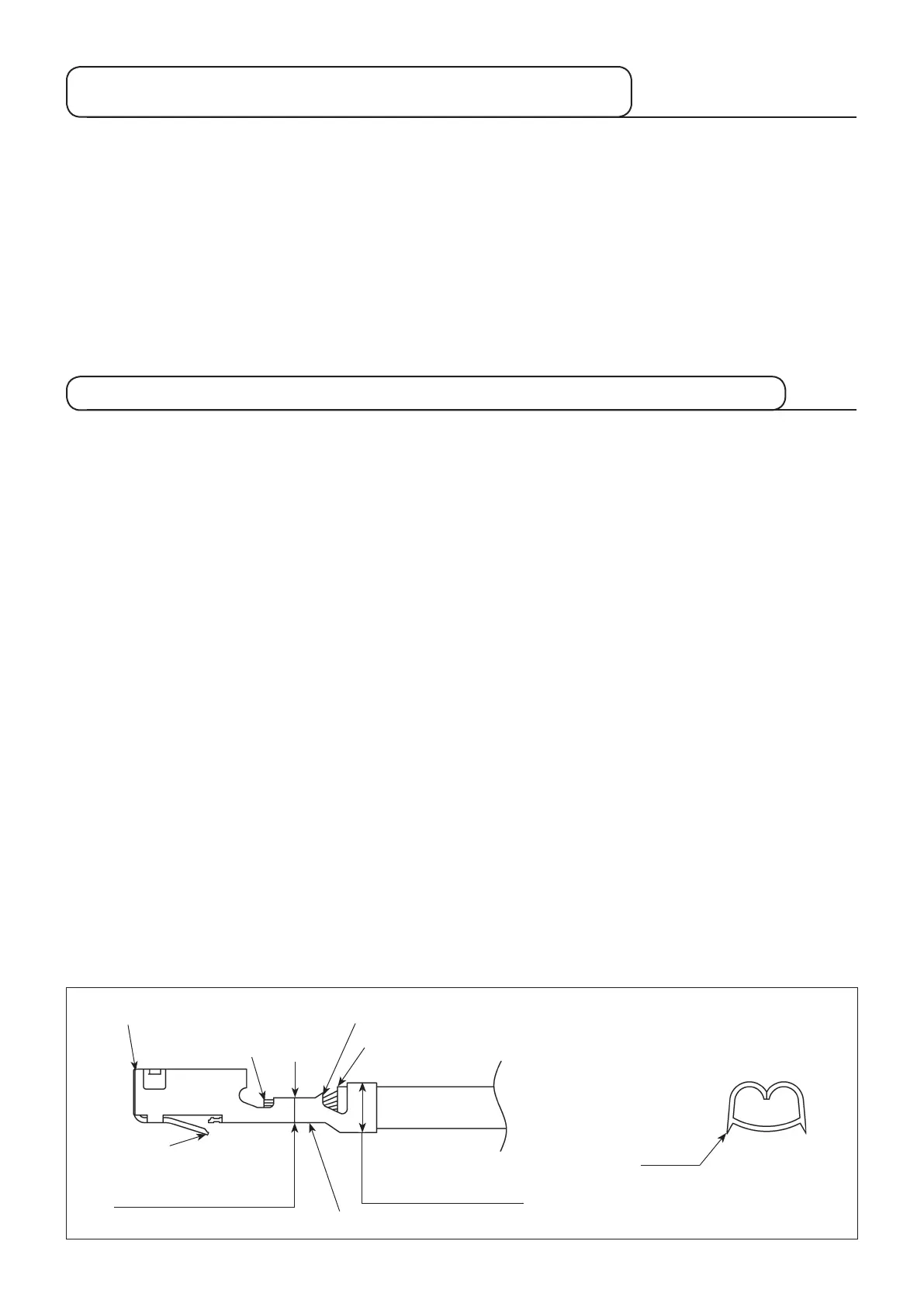
ベルマウス /
Bellmouth
45
被覆位置
/ Position of outer insulation
3
芯線位置 /
Protrusion of conductor
7
端子コンタクト部 /
Contact section of contact
⑧ランス /
Lance
1
芯線部クリンプハイト
/
Contact conductor sectionsection
of crimp heightcrimp height
!0
肌荒れ
/ Rough surface
1
被覆部クリンプハイト /
Outer insulation sectionOuter insulation sectionsection
of crimp heightcrimp height
9
バリ /
Burr
2-6. 圧着後の端子形状の確認 /
Conrmationoftheshapeofcontactaftercrimping
2-6-1. 良品の基準 /
Standards for acceptable crimp
* 規格値については「8. 圧着条件及び圧着品質基準表」を参照のこと。
*
See " 8. Table of crimping conditions and crimping quality standard" for the specied values.
1
クリンプハイトが規格内にあること。
2
ベルマウスが適正な大きさであること。
3
芯線の突き出しは適正であること。
4
ワイヤーバレルに被覆の食い込み(深打ち)となっていないこと。
5
被覆はインシュレーションバレルに適正に圧着されていること。
6
芯線がワイヤーバレルからはみ出していないこと。
7
端子のコンタクト部に変形がないこと。
8
ランスに変形がないこと。
9
ワイヤーバレル部に大きなバリが無いこと。
!0
圧着部に亀裂やバレル外面の肌に荒れが無いこと。
!1
端子の曲りが「8. 圧着条件及び圧着品質基準表」の規格を満足していること
1
The crimp height is in the specied range.
2
The bellmouth has an is correct size.
3
The protrusion of the conductor is correct.
4
The outer insulation is inserted in the conductor barrel.
5
The
outer insulation
is correct crimped in the insulation barrel.
6
The conductor does not protrude from the wire barrel.
7
The contact section of the contact is not deformed.
8
The lance is not deformed.
9
The wire barrel has no noticeable burr.
!0
The nished crimped section is free from any material crack or rough surface on the outside of the barrel.
!1
The bend angle in the contact is as specied in " 8. Table of crimping conditions and crimping quality standard".