Figure 2.3 - Batteries wiring connection
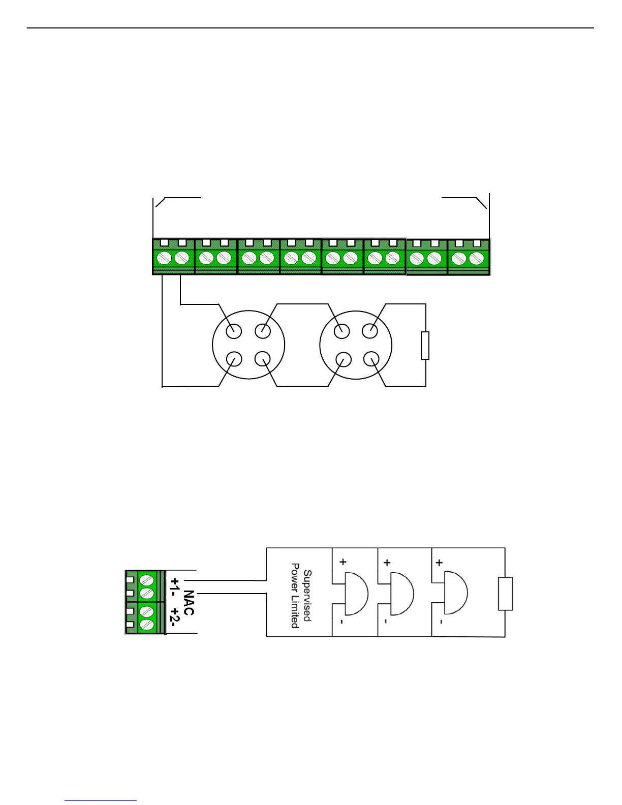
2.5 Zone Installation
The panel has either 4, 8 or 16 class B conventional input zones. Wire the smoke, heat
or multi detector positive terminals to the terminal labeled “+” and the negative
detector terminals to the terminal labeled “-“ as shown in figure 2.4 which shows the
panel. Each active zone requires a 4K7end of line (EOL) resistor at the very end of
the zone as shown in figure 2.4.
Figure 2.4 - Detectors wiring connection
2.6 NAC (Sounder) Output Circuit Installation
The control panel has 2 built-in output notification appliance circuits (NAC).
Figure 2.5 shows output circuit 1 wired as a class B NAC output. Observe the
polarity of the wiring and the placement of the 10K end of line (EOL) resistor located
at the very end of the class B wiring.
Figure 2.5 – Sounder/bell wiring connection
2.7 Relay Outputs
Each panel has 2 forms C relays, the relays are dedicated to common alarm (auxiliary
contacts) and common fault functions. All 2 relay outputs (Alarm and fault relays)
carry the same voltage and current ratings. The relays are rated 2 amps at 30VDC.
- 10 -
4K7
EOL
SENSE ZONES(DETECT/CALL POINTS)
+1- +2- +3- +4- +5- +6- +7- +8-
--_
in + out+
in – out-
in – out-
in + out+
10K/1W