Connecting The Amplier to the Lync6
9
How to Connect
(CONT.)
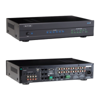
Use the Variable Line Outputs on the Lync to connect to the Line Inputs on the ampliers for each zone. We
include six 3’ shielded stereo patch cables with the Lync for this purpose. The diagram above shows the recom-
mended connection to our DMA-1240 12-channel amplier.
3’ Shielded Stereo
Patch Cables
Speaker Connections
Right
Right Right Right Right Right
Left
Left Left Left Left Left
Power
123456 123456
789101112
Zone Status Source Signal Strength
AC 120V~60Hz
FUSE T2AL/250V
Power Consumption: 160W
ROUTED IR OUT
SOURCE INPUT
KEYPAD PORTS
7
8
9
10
11
12
MP3
L
ZONE 1 PREOUT ZONE 2 PREOUT ZONE 3 PREOUT ZONE 4 PREOUT ZONE 5 PREOUT ZONE 6 PREOUT
MONO STEREO MONO STEREO MONO STEREO MONO STEREO MONO STEREO MONO STEREO
R
LRLR
LRLR
LRLRLRLR
LRLRLR
R
L
43
2
1
56
IR IN
RS232
INTERFACE
GLOBAL
IR OUT
12V/DC
TRIGGER
100mA
IN OUT
System
TRIGGER
AC/DC 3-20V
Mute
Made in Ta iwan
CAUTION
To Prevent Electric Shock,
Do Not Remove Cover. No
User-Serviceable Parts Inside,
Refer Servicing To Qualified
Service Personnel.
WARNING
To Prevent Fire Or Shock
Hazard, Do Not Expose This
Unit To Rain Or Moisture.
FIXEDVARIABLE
IR IN
SOURCE 7
Left Right
Out 2
Out 1
In 2
In 1
1
2
3
Line In
4
5
6
7
8
9
10
1 1
12
Line In
1 2 Line
Bridged
L L+R RL L+R RL L+R RL L+R RL L+R RL L+R RL L+R RL L+R RL L+R RL L+R RL L+R RL L+R R
On
Auto On
3-30V
AC/DC
Tr igger In
AC 120V-60Hz
Fuse: T15A/250V
Power Consumption: 1200W
12V DC
Control
Out
Trigger
1 2 Line1 2 Line 1 2 Line 1 2 Line 1 2 Line 1 2 Line 1 2 Line 1 2 Line 1 2 Line 1 2 Line1 2 Line
Line In Line In Line In Line In
Bridged Bridged Bridged Bridged Bridged
DMA-1240
Power
Vol 1 Vol 2 Vol 3 Vol 4 Vol 5 Vol 6 Vol 7 Vol 8 Vol 9 Vol 10 Vol 1 1 Vol 12
Amplier Settings
Two side-by-side amplier channels are used for each zone. One side is set to amplify the Right channel of a stereo
signal and the other side is set to amplify the Left side of a stereo signal. In our diagram, channel 1 is set to amplify the
Right channel and channel 2 is set to amplify the Left channel for the speakers in Zone 1.
Level: Our multi-channel ampliers include separate level knobs for each channel. Turn the rotary Level knob clockwise
to increase the power output of each channel. In most cases, setting this knob around the 2:00 position will achieve the
amplier’s maximum rated power output level. You can articially add gain to a weak line level input signal by turning this
level beyond this point, but in most cases it is not necessary and not recommended. Best Practice: with the Level knob all
the way down (counter-clockwise), set the LyncPad volume level to 60 (max). Next, using a strong input signal (such as
from a DVD player or TV set-top box), have a friend slowly adjust the Level knob(s) up (clockwise) until the volume level
in the zone is as loud as you would ever want it. Leave the Level knob at this setting. This is the most efcient way to
operate your amplier and also prevents a zone from accidentally operating at too loud of volume.
Input Selection Switch: Set to “Line”.
L, L+R, R Switch: When the “Line” input is used, this switch is inactive so the setting is irrelevant. However, you might
want to set odd numbered channels to Right (R) and even channels to Left (L) just to make it easier to recall which Line
Output from the Lync is being sent to each channel.
 Loading...