16
How to Connect
(CONT’D)
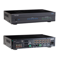
The Lync controller includes 5 Routed IR emmitter outputs and 1 Global IR emitter output. Routed IR means that IR signals
are routed only to the Source currently selected on a LyncPad. This allows you to have two of the same source (such as
two DirecTV or Cable boxes) but only control the one you want. Global IR will output all of the IR signals allowing you to
control a device even if it is not selected on the Lync. The eye on each LyncPad will pass IR signals to the source selected
AND out through the Global IR output. The IR eye connected to the IR IN on the back of the Lync will only pass IR signals
out through the Global IR output.
Lync (back)
Dual IR Emitter
Single IR Emitter
HTD Whole-House
Audio Controller
HTD 12-Channel
Amplifier
CD Changer
Music Server
Any IR Controlled
Device
Home Theater Receiver
Direct TV box 2
Direct TV box 1
Controlled by
global IR output
AC 120V~60Hz
FUSE T2AL/250V
Power Consumption: 160W
ROUTED IR OUT
SOURCE INPUT
KEYPAD PORTS
7
8
9
10
11
12
MP3
L
ZONE 1 PREOUT ZONE 2 PREOUT ZONE 3 PREOUT ZONE 4 PREOUT ZONE 5 PREOUT ZONE 6 PREOUT
MONO STEREO MONO STEREO MONO STEREO MONO STEREO MONO STEREO MONO STEREO
R
LRLR
LRLR
LRLRLRLR
LRLRLR
R
L
43
2
1
56
IR IN
RS232
INTERFACE
GLOBAL
IR OUT
12V/DC
TRIGGER
100mA
IN OUT
System
TRIGGER
AC/DC 3-20V
Mute
Made in Ta iwan
CAUTION
To Prevent Electric Shock,
Do Not Remove Cover. No
User-Serviceable Parts Inside,
Refer Servicing To Qualified
Service Personnel.
WA RNING
To Prevent Fire Or Shock
Hazard, Do Not Expose This
Unit To Rain Or Moisture.
FIXEDVARIABLE
IR IN
SOURCE 7
Controlled by
routed IR output
To Music Server
To CD Changer
To Direct TV Box 1
To Direct TV Box 1
To Home Theater Receiver
and Any IR Controlled Device
Dual IR Emitter
Dual IR Emitter
Single IR Emitter
HTD Whole-House
Audio Controller
HTD 12-Channel
Amplifier
CD Changer
Music Server
Any IR Controlled
Device
Home Theater Receiver
Direct TV box 2
Direct TV box 1
Controlled by
global IR output
Controlled by
routed IR output
AC 120V~60Hz
FUSE T2AL/250V
Power Consumption: 160W
ROUTED IR OUT
SOURCE INPUT
KEYPAD PORTS
7
8
9
10
11
12
MP3
L
ZONE 1 PREOUTZONE 2 PREOUTZONE 3 PREOUTZONE 4 PREOUTZONE 5 PREOUTZONE 6 PREOUT
MONO STEREO MONO STEREO MONO STEREO MONO STEREO MONO STEREO MONO STEREO
R
LRLR
LRLR
LRLRLRLR
LRLRLR
R
L
43
2
1
56
IR IN
RS232
INTERFACE
GLOBAL
IR OUT
12V/DC
TRIGGER
100mA
IN OUT
System
Mute
Made in Ta iwan
CAUTION
To Prevent Electric Shock,
Do Not Remove Cover. No
User-Serviceable Parts Inside,
Refer Servicing To Qualified
Service Personnel.
WARNING
To Prevent Fire Or Shock
Hazard, Do Not Expose This
Unit To Rain Or Moisture.
FIXEDVARIABLE
To Music Server
To CD Changer
To Direct TV Box 1
To Direct TV Box 1
To Home Theater Receiver
and Any IR Controlled Device
Dual IR Emitter
IR Emitters are sold separately
Connecting IR Emitters to devices
Although the previous diagrams show the IR emitters placed
near the devices that you wish to control, these diagrams are
meant to basically show how the emitters/receiving eyes t into
your whole-house audio setup.
The emitters are packaged along with double sided tape which
allow the emitters to attach directly to the devices you wish to
control. These emitters should be placed directly onto the IR
receiving eye of the devices. The diagrams below show speci-
cally where these IR emitters should be placed.
The IR emitters shown have a ash-back feature built into the
device to visually signal when a command has been “passed
through” the system. This ash-back indicator is located on the
top side of the emitter. The actual emitting eye within the emitter
is located on the bottom portion of the emitter. This is why the
emitters should be attached on top of the device’s receiving eye
that you wish to control.
To Whole-house
Audio Contoller
To Whole-house
Audio Contoller
Use the double-sided tape included with the IR emitter
to attach the emitter to the devices’s IR recieving eye.
This emitter is attached in the appropriate location. The emitter ca-
ble is running under this device to the whole-house audio controller.
This is a side view showing
how the IR emitter should be
attached to the device that is
being controlled.
IR Emitters
Single IR Emitter
Dual IR Emitter
 Loading...