21
LP- 293 REV. 9.2.14
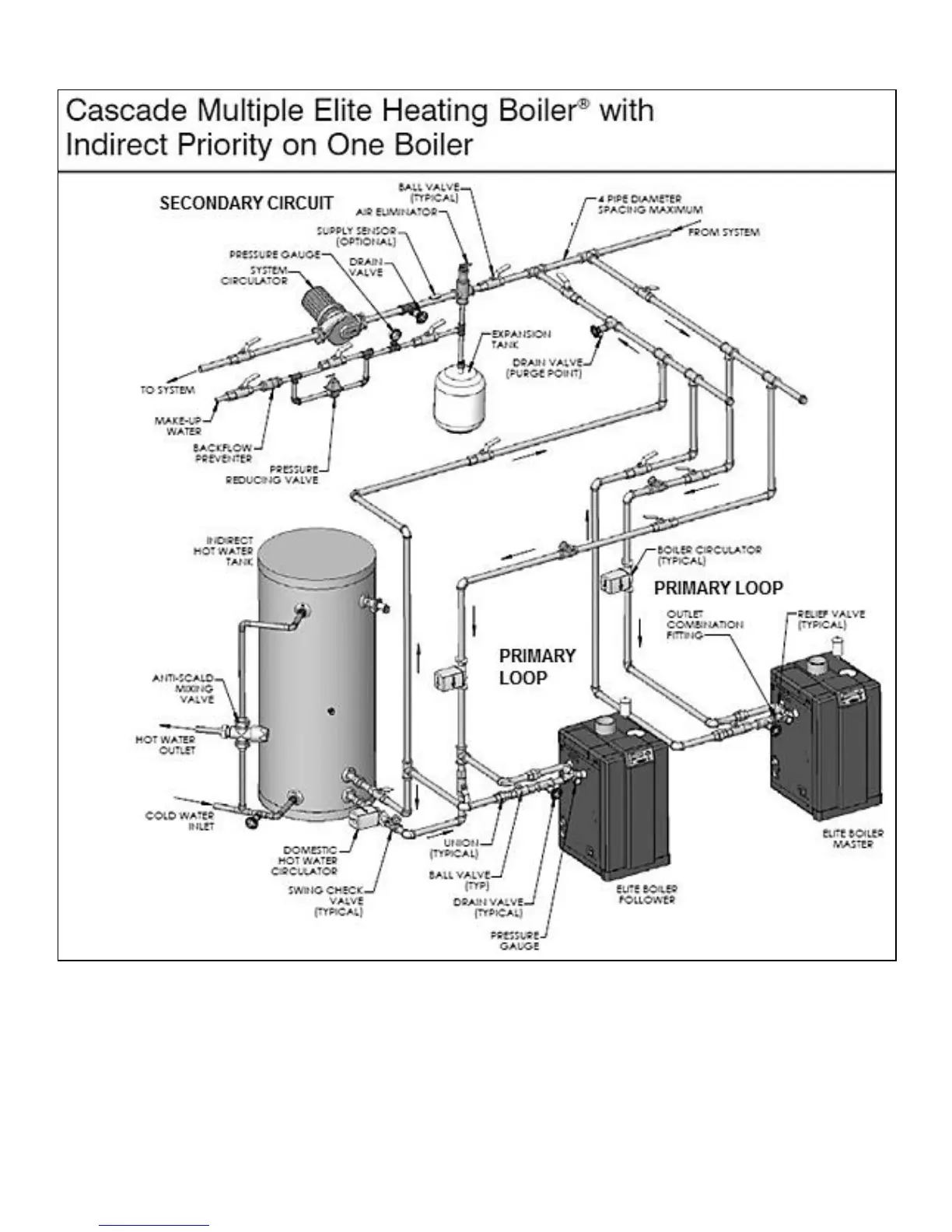
Figure 7 – LP-293-Q
NOTES:
1. This drawing is meant to show system piping concept only.
2. A mixing valve is recommended if the DHW temperature is set above 119
o
F.
3. Install a minimum of 12 diameters of straight pipe upstream of all circulators.
4. Piping shown is Primary/Secondary.
5. System flow (secondary loop) should be greater than the boiler primary loop flow. In all cases, the boiler primary loop flow rate must
be maintained above the minimum flow rates published in this manual.
6. Installations must comply with all local codes.
7. In Massachusetts, a vacuum relief valve must be installed in the cold water line per 248 CMR.
8. Reference Figure 10 to determine manifold pipe sizing.




 To Next Page