7
Figure 3
4
8
5
3
2
2
7
7
6
1
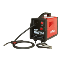
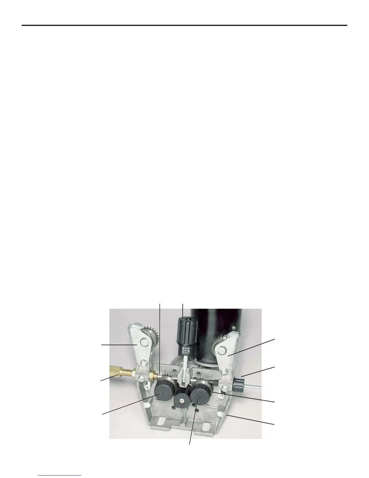
Feeding the Welding Wire (See Fig. 3)
1. When using 10 lb., 8" diameter spools, remove the red
nut and install the spacer on the shaft. Do not use the
spacer on 30 lb. spools. Place the welding wire on the
spool holder so it unravels from the bottom. Install
the red nut. When using 10 lb. spools, the pin in the
shaft will not engage the roll of wire.
2. Loosen the wire from the spool. Be extremely careful
not to let the end of the wire go. Cut off the bent end
of the wire to expose a piece of straight wire.
3. Swing the pressure release handle (1) down, and lift the
pressure roller assemblies (2) up and out of the way.
4. Feed the wire into the inlet wire guide (3), across the drive
rolls (4), and into the guide tube (5). (At this time it is a
good idea to check that the drive roll is set to the correct
groove for the wire size you are using. If not, see Changing
the Drive Roll. Continue to feed the wire into the guide tube
until two or three inches of straight wire protrudes from the
front of the central adapter block.
5. Swing the pressure roller assemblies (2) back into
position. Make sure that the wire is positioned in the
groove of the drive rolls (4). Unscrew the pressure
release handle (1) until most of the pressure on the
pressure roller has been released.
6. Remove the contact tip and gas nozzle from the welding
gun. Turn the wire feed rate to 6. Depress the trigger on
the welding gun. At this point, the wire feed should not be
consistent because there is not enough pressure on the
pressure roller. Slowly tighten the pressure roller adjusting
screw until the wire feeds evenly without slipping. Then
tighten an additional 1/4 turn for steel. No additional
tightening is necessary for aluminum. DO NOT
OVERTIGHTEN!
Continue feeding the wire until it appears at the tip of
the welding gun. Check your wire size and install the
correct contact tip. Install the gas nozzle.
7. Next, the tension on the wire drive brake must be set
correctly. The wire drive brake keeps the spool of wire
from continuing to rotate after we have stopped welding.
In the center of the shaft on which the wire mounts, is a
bolt. This bolt puts tension on a spring, which in turn puts
tension on the shaft, acting as a brake for the spool of wire.
Set the wire feed rate to maximum, and using a 1/2" socket,
adjust the tension on the wire drive brake so the spool will
continue to rotate 1/4 to 1/2 turn after you have released the
trigger, but not rotate so much that the wire begins to fall
off the spool. If you are using 10 lb. 8" diameter spools,
more than likely you will have to reduce the tension on the
drive brake.
8. Bend the welding wire 90 degrees and hold the welding
gun perpendicular to a non-conductive surface (concrete
floor) so the wire will not feed. While looking at the wire
feed mechanism, momentarily depress the trigger. The
drive roll should slip and act as a clutching mechanism. If
not, the drive roll will push the wire out between the roller
and the guide tube. This is known as "bird nesting". If bird
nesting occurs, the pressure roller has been adjusted too
tightly. When properly adjusted, the drive roll will slip, and
“bird nesting” will never occur.
 Loading...