Electrical Connection
Your HTP MIG 2400 will only operate when PROPERLY
connected to a 220 volt, single phase power source wired
for a minimum of 40 amps. A qualified electrician in
accordance with the National Electrical code and local codes
and ordinances should do all electrical connections. When
connecting your MIG 2400 the green or yellow-green wire
MUST BE CONNECTED TO GROUND, OR SERIOUS
INJURY MAY RESULT.
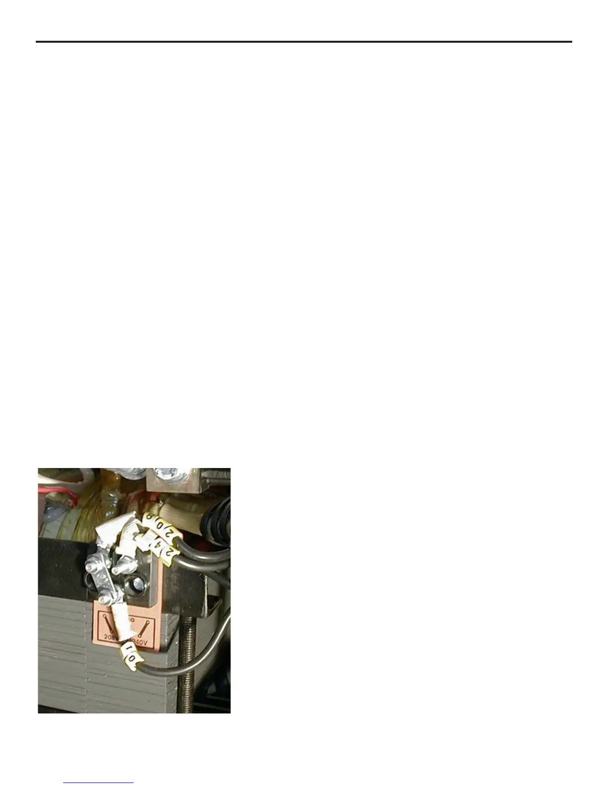
The welder has a line voltage adjustment on the main
transformer similar to Fig. 1. The correct line voltage must be
selected in order for your welder to operate properly.
To set your line voltage adjustment, be sure the welder is
unplugged. Remove the left-hand side panel as you are facing
the front of the welder. Locate the line voltage adjustment.
Measure your input line voltage with a voltmeter. If your
voltage measures 225 volts or less, the metal tabs (a) should
be set to the 208-v position as shown in fig. 1. If you line
voltage is 226 volts or higher, the metal tabs (a) should be
moved to the 240-v position. In order to move the metal tabs,
it is necessary to remove two 7mm nuts first.
Note: Your welder has a circuit breaker installed at the rear
of the machine, just above where the input power cord goes
into the welding machine. If, after connecting the machine to
a 220 volt power supply and turning the power switch on, the
machine does not come on, be sure the circuit breaker is in the
ON position.
Front Panel Controls
1. Wire Feed Rate – the wire feed rate is infinitely
adjustable and controls the wire speed. Minimum is
the slowest and maximum is the fastest. The wire feed
rate will depend on the wire diameter and the power
switch position. The wire speed setting is tuned into
the proper welding sound. A hissing, blowing sound
with a ball of molten wire forming at the end of the
wire and then dropping off indicates the wire feed rate
is too slow. A loud cracking noise with the wire
pushing the nozzle away from the work indicates the
wire feed is too fast. The proper wire feed rate is
obtained when a steady buzzing noise is heard while
welding.
2. Weld Time – When the weld time knob is switched
ON, the welding machine is in the spot welding mode.
In the spot weld mode, the welder will weld for a
predetermined time period and stop. The welder will
not weld again until the trigger is released and
depressed. The spot weld time is determined by the
weld time knob. Position 1 is a weld time of
approximately 1/2 second and position 9 is a weld
time of approximately 2 1/2 seconds.
3. Digital Display Selector Switch – When this switch is
set to the “V” setting, the digital display (#4) will
display the welding voltage. When this switch is set to
the “A” position, the digital display will display the
welding amperage.
4. Digital Display – The digital display will display either
the welding voltage when the digital display switch (#3) is
set to “V”, or the welding amperage when the digital
display switch (#3) is set to “A”. This allows you to
more precisely monitor your welding parameters.
5. On-Off Switch – This switch controls the input power
to your welder. The On-Off switch allows you to turn
the welding machine off, leaving all the settings intact,
ready for your next use.
Turning the switch to the ON position will illuminate
an indicator lamp in the On-Off switch and activate the
cooling fan. If the indicator lamp is not lit when the
On-Off switch is in the ON position, check to make
sure that the machine is properly connected to an
electrical outlet in good working order. Also be sure to
check the circuit breaker at the rear of the welder is in
the ON position.
4
Figure 1
 Loading...