42
LP- 428 REV. 9.2.14
PART 7 – FIELD WIRING
ELECTRICAL SHOCK HAZARD - Turn off electrical power supply at service entrance panel before making any electrical connections.
Failure to do so can result in severe personal injury or death.
Wiring must be N.E.C. Class 1. If original wiring supplied with the boiler must be replaced, use only UL Listed TEW 105
o
C wire or
equivalent. Boiler must be electrically grounded as required by National Electrical Code ANSI/NFPA 70 – Latest Edition.
In order to ease future servicing and maintenance, it is advised to label all wires. Wiring errors can cause improper and dangerous
operation. Failure to follow these instructions could result in property damage or personal injury.
A. INSTALLATION MUST COMPLY WITH:
1. National Electrical Code and any other national, state, provincial or local codes or
regulations.
2. In Canada, CSA C22.1 Canadian Electrical Code Part 1, and any local codes.
B. FIELD WIRING
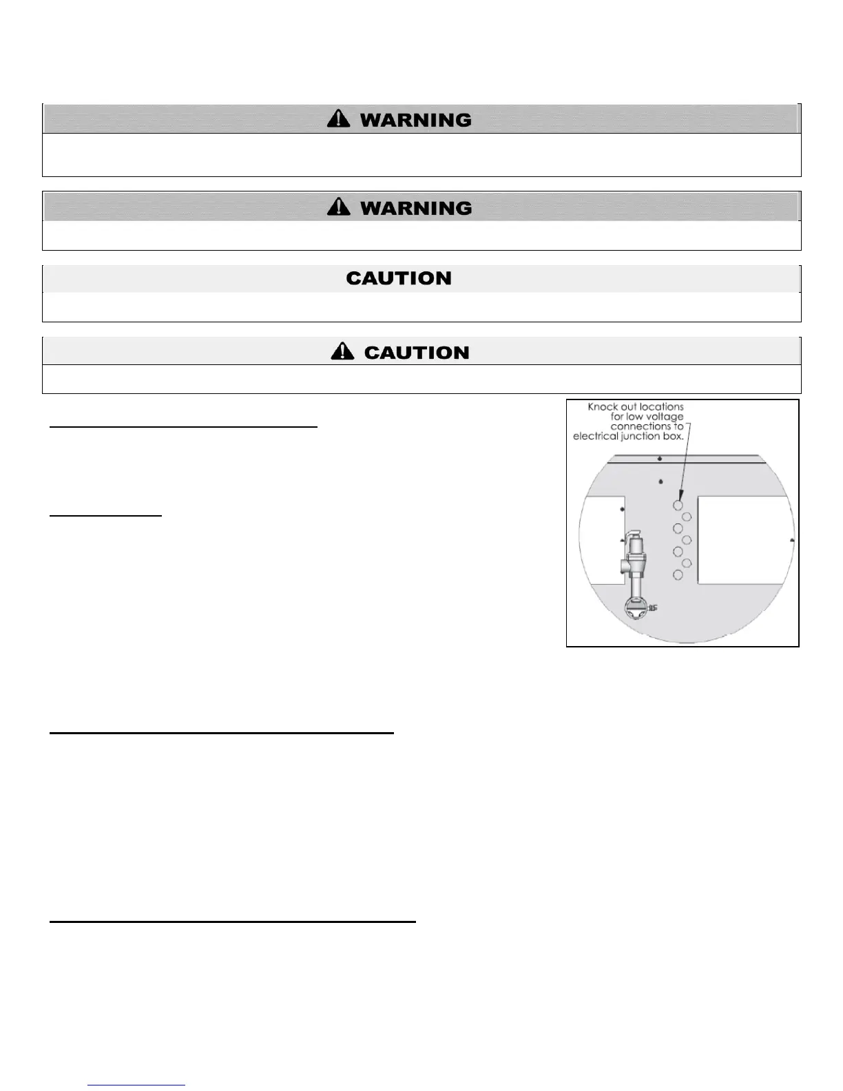
All connections made to the boiler in the field are done inside the electrical junction box
located on the side of the unit. The electrical junction box is located on the left side of both
boilers. Multiple knockout locations are available to route field wires into and out of the
electrical junction box. Most of the electrical field connections are made to the bottom
boiler. If it is required to connect to the top boiler, it will be clearly marked in this section.
The control system used in the Mod Con 1000 and 1700 series of boilers is capable of
directly controlling 3 pumps as shipped. Each pump output can provide a maximum of 3
amps at 120 volts. This output is sufficient to operate the coil of a motor starter correctly
sized for the pump or pumps used in the system design.
The electrical junction box has separate, clearly marked terminal strips for line voltage and low voltage wiring. Special jacks are
provided for trouble-free cascade system wiring using standard CAT3 or CAT5 patch cables.
C. LINE VOLTAGE WIRING FOR STANDARD BOILER
1. Connect the incoming power wiring to the line voltage terminal strip in the electrical junction box at terminals LINE 120V, Neutral, and
Ground of the bottom boiler (shown in Figure 27).
2. A line voltage fused disconnect switch may be required to be externally mounted and connected according to local wiring codes.
3. Connect the central heating pump motor starter coil to the terminals marked BOILER HOT, BOILER NEUT, and BOILER GRD in the
bottom boiler.
4. If using DHW, connect the domestic hot water pump to the terminals marked DHW HOT, DHW NEUT, DHW GND on the bottom
boiler. The connections shown are suitable for a maximum continuous pump draw of 3 amps at 120 volts. If a pump requires more
current or voltage than the 120 volts supplied, an external motor starter or contactor will be required.
D. ALARM CONNECTIONS (TOP BOILER CONNECTION)
The Mod Con control system includes a dry contact alarm output. This is an SPDT circuit, rated at 5 amps at 120 volts. This contact can
be used to activate an alarm light or bell, or notify a building management system if the boiler goes into a lockout condition. The circuit
between the ALARM COM and NC terminals is closed during normal operation and the circuit between ALARM COM and NO is open
during normal operation. The example connections depicted in Figure 27 show two 120 volt lights connected to the alarm terminals.
One light will be on when the boiler is in normal mode and the other light will turn on when the boiler is in lockout mode. NOTE: This
alarm connection will activate when either boiler is in a LOCKOUT condition.
To avoid electrical shock, turn off all power to the appliance prior to opening an electrical box within the unit. Ensure the power remains
off while any wiring connections are being made. Failure to follow these instructions could result in component or product failure,
serious injury, or death. Such product failure IS NOT covered by warranty.