57
LP- 428 REV. 9.2.14
SYS FREEZE PROT
PROTECT OFF 26
NOTE: This parameter is only present if the boiler is a cascade master. Allows the user to set the freeze protection
when a system pump is used. Factory Default: OFF. Selection of temperature activates freeze protection. (Range:
OFF, -40
o
F – 104
o
F).
Allows the user to set the control to display an error message if the system sensor is open or shorted. NOTE: This
error does not stop the boiler (or boilers) from running. Factory Default: ON (Range: ON / OFF).
Allows the user to set freeze protection on the boiler. Factory Default: ON (Range: ON / OFF).
DHW MODULATE MODE
NORMAL MOD 29
This parameter controls how the boiler modulates for a DHW demand. In NORMAL MOD mode, the boiler will
modulate down from high fire when there is a DHW demand. In LOW MOD mode, the boiler will modulate up from low
fire when there is a DHW demand. This mode is useful to minimize short cycling when a large boiler and small indirect
tank are used together. Factory Default: NORMAL MOD (Range: NORMAL MOD / LOW MOD).
Allows for a non HTP boiler to be controlled when the cascade output has risen above the percent of the cascade firing
rate set in this parameter. Factory Default: Off (Range: 50% - 100%).
SYSTEM SENSOR MODE
OFF 31
Suppresses the ‘NO FOLLOWER’ message on the display if the boiler is used as a cascade master boiler with no
follower boilers connected. Factory Default: OFF (Range: ON / OFF).
Allows the user to select a service date or time based on the boiler run hours to program the boiler maintenance
schedule. Factory Default: OFF (Range: Date or Run Hours). NOTE: Without setting this function, Functions
33/34/35/36 will not display.
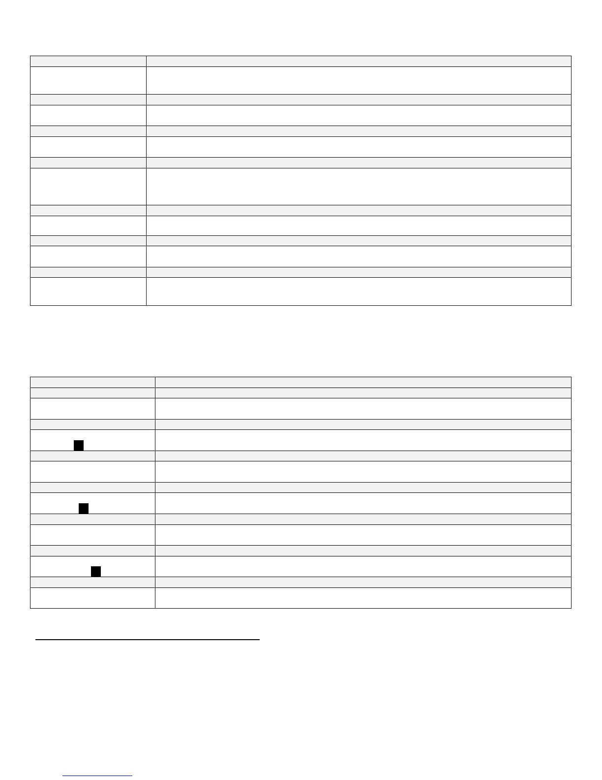
Table 15 – System Setting Menu Screens
NOTE: For the following functions, you must have your maintenance function turned on.
To change, press ENTER. The left most digit will begin to blink. Use the up ▲ or down ▼ arrows to change the digit. Use the
arrow keys to switch between digits. When you’ve made your selection, press ENTER again.
SERVICE SCHEDULE
YEAR 00/00/2000 33
Allows the user to set the year of the next service reminder.
SERVICE SCHEDULE
10000’s 000000h 33
Allows the user to set the left two digits of the amount of run hours before next service reminder.
SERVICE SCHEDULE
MONTH 00/00/2000 34
If the date function was selected, this function allows the user to program the month. If you selected the run hour
function, you will need to program 10,000 hours, if required.
SERVICE SCHEDULE
10000’s 000000 34
Allows the user to set the two middle digits of the amount of run hours for the next service reminder.
SERVICE SCHEDULE
DAY 00/00/2000 35
Allows the user to set the day of next service reminder.
SERVICE SCHEDULE
10000’s 000000 35
Allows the user to set the 2 right digits of the amount of run hours for the next service reminder.
TELEPHONE #
000 000 0000 36
Allows the user to input a telephone number that will be displayed when maintenance is required.
Table 16 – Maintenance Reminder Function Screens
G. RESETTING THE MAINTENANCE SCHEDULE
When the system control flashes MAINTENANCE REQUIRED, it is advisable that you call for service. After the service is performed,
reset the schedule for the next required service by using the following steps.
Press ENTER on the display for 3 seconds. The Menu code will appear as 000. This does not change. Press ENTER again. SERVICE
SCHEDULE RESET will be displayed. Using the right arrow key scroll to the selection of year or hours. Select enter to reset the
mode you are in. Use the up ▲ or down ▼ arrow key for each adjustment then select ENTER when reset is complete.