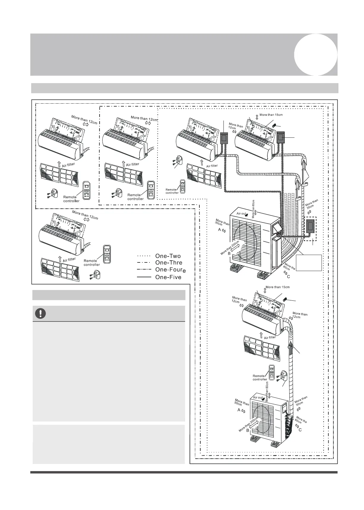
Outdoor Unit
Installation Diagram
4
Installation Diagram
Installation
plate
Mounting screw
ST3.9
×25-C-H
Refrigerant
pipe
Remote
controller
holder
Clip anchor
(2)
•
This illustration is for demonstration
purposes only.
The actual shape of your air condtioner may
be slightly dierent.
Copper lines must be independently insulated.
•
•
CAUTION
•
To prevent wall damage, use a stud nder to
locate studs.
A minimum pipe run of 3 metres is required
to minimise vibration & excessive noise.
Two of the A, B, and C air circulation pathways
must be free from obstructions at all times.
•
•
NOTE: The installation must be performed in
accordance with the requirement of local and
national standards. The installation may be
slightly dierent in dierent areas.
Safety Precautions
1
2
3
5
4
1
Installation plate
Mounting screw
ST3.9
×25-C-H
Clip anchor
(1)
Remote
controller
holder
5 4 3
2
The maximum
amount of the
connection cables is 5.
This section is for
reference only.
Air-break Switch
Drainage
Pipe
Air-break
Switch
Outdoor Unit
Power Cable