Figures
Figure 1-1 Wearing an ESD wrist strap...............................................................................................................1-5
Figure 1-2 Lifting Weights.................................................................................................................................1-10
Figure 1-3 Slant angle........................................................................................................................................1-10
Figure 1-4 One meter higher than the eave........................................................................................................1-11
Figure 2-1 APM30H (connected to the IBBS200T) working with a distributed base station.............................2-6
Figure 2-2 APM30H working with the 3-RFU RF cabinet..................................................................................2-7
Figure 2-3 APM30H working with the 6-RFU RF cabinet..................................................................................2-8
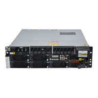
Figure 3-1 APM30H.............................................................................................................................................3-2
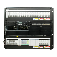
Figure 3-2 Internal structure of the APM30H......................................................................................................3-3
Figure 3-3 Cable holes of the APM30H...............................................................................................................3-3
Figure 3-4 HEUA.................................................................................................................................................3-4
Figure 3-5 Ports on the HEUA.............................................................................................................................3-5
Figure 3-6 HPMI..................................................................................................................................................3-6
Figure 3-7 Ports on the panel of the HPMI..........................................................................................................3-6
Figure 3-8 Ports on the PDU................................................................................................................................3-9
Figure 3-9 PMU..................................................................................................................................................3-11
Figure 3-10 Ports on the front panel of the PMU...............................................................................................3-12
Figure 3-11 Backplane of the PMU...................................................................................................................3-13
Figure 3-12 Right panel of the PMU..................................................................................................................3-15
Figure 3-13 Panel of the PSU (AC/DC).............................................................................................................3-16
Figure 3-14 Power subrack.................................................................................................................................3-18
Figure 3-15 Core of the heat exchanger.............................................................................................................3-19
Figure 3-16 Fan..................................................................................................................................................3-20
Figure 3-17 Heater..............................................................................................................................................3-21
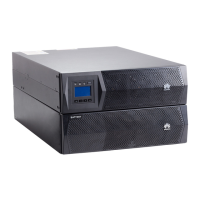
Figure 4-1 IBBS200T...........................................................................................................................................4-2
Figure 4-2 Internal structure of the IBBS200T....................................................................................................4-3
Figure 4-3 TEC cooler..........................................................................................................................................4-4
Figure 4-4 Junction box........................................................................................................................................4-5
Figure 4-5 Internal structure of the junction box..................................................................................................4-6
Figure 4-6 Signal transfer terminals.....................................................................................................................4-7
Figure 4-7 Batteries..............................................................................................................................................4-7
Figure 5-1 TMC11H.............................................................................................................................................5-2
Figure 5-2 Structure of the TMC11H...................................................................................................................5-3
APM30H
User Guide Figures
Issue 01 (2008-10-08) Huawei Proprietary and Confidential
Copyright © Huawei Technologies Co., Ltd
iii
 Loading...