Do you have a question about the Huawei TP482000B-N20B1 and is the answer not in the manual?
Describes the DC power system features, configurations, components, and maintenance methods.
Lists the professionals for whom the document is intended.
Defines the symbols used in the document.
Provides general safety instructions for installation, operation, and maintenance of the equipment.
Details precautions for personal safety during equipment operations, including electric shock and proper handling.
Outlines the qualifications and training needed for personnel working with the equipment.
Covers grounding requirements and AC/DC power safety precautions.
Specifies conditions for safe and proper installation, including temperature, atmosphere, and location.
Details safety procedures and precautions for working at heights.
Covers safety precautions for hoisting devices and general mechanical handling.
Provides safety guidelines for using ladders during installation and maintenance.
Outlines safety precautions for drilling and moving heavy objects to prevent injuries.
Provides guidelines for battery installation, short circuit prevention, and general handling.
Covers hazards from flammable gas, electrolyte leaks, and specific safety for lithium batteries.
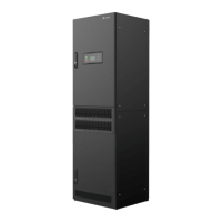
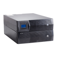
Introduces the TP482000B as a high-performance indoor telecom power system.
Details the key features of the TP482000B power system, including flexibility, density, and efficiency.
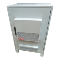
Lists typical and flexible configurations for single TP482000B cabinets.
Presents typical configurations for multi-cabinet setups of the TP482000B series.
Illustrates the physical arrangement of interconnected TP482000B cabinets in a system.
Details the configurations for the TP482000B-N20B1 combined cabinet, including load routes.
Describes how to configure AC input, output, and emergency lighting for TP483000D AC cabinets.
Explains configuration of battery and load routes for TP483000D DC cabinets.
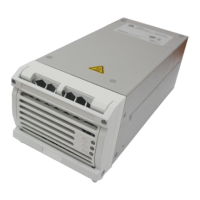
Explains the function of the rectifier and its indicator status for AC input and faults.
Covers the SMU05A panel, buttons, and their functions for system monitoring.
Describes the function of the power distribution monitoring unit for AC/DC power distribution and its features.
Provides a step-by-step guide for removing and installing a rectifier module.
Details procedures for replacing the SMU05A unit and its main control board.
Explains the process of replacing the Liquid Crystal Display (LCD) unit on the SMU.
Provides instructions for replacing the button board on the SMU unit.
Details steps for replacing the signal sampling board within the power distribution monitoring unit.
Guides replacement of LCD and button board on the power distribution monitoring unit.
Provides instructions for replacing the signal transfer board.
Details the procedure for replacing the AC Surge Protection Device (SPD).
Guides the replacement of circuit breakers within the system.
Explains the process of replacing fuses in the system.
Outlines common DC output faults that may require emergency measures.
| Brand | Huawei |
|---|---|
| Model | TP482000B-N20B1 |
| Category | Power Supply |
| Language | English |