7
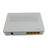
Step 1 Use an optical fiber to connect the OPTICAL port on the GPON terminal to
the optical port in the wall.
Step 2 Use a network cable to connect the LAN port to a PC or the Ethernet port on
the IP STB.
Step 3 Use a phone line to connect the TEL port to a phone or fax machine.
Step 4 Use a power adapter to connect the POWER port to the power socket.
Step 5 Use a USB data cable to connect the USB port to the USB storage device.
Step 6 Press the ON/OFF power switch.
Step 7 Press the WLAN switch to enable the Wi-Fi access function. By default, this
function is enabled.
Step 8 Press the WPS switch to enable the WPS encryption function.
Connecting Cables
Refer to the preceding cable connections of each product and select the following
corresponding steps to connect the GPON terminal.
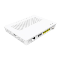
The optical connector connected to the OPTICAL port on the HG8245 is an SC/APC
connector, and the type of the optical connector connected to the optical port in the
wall is determined by practical conditions.
The preceding figure connects the power adapter as an example. When the backup
battery unit is used, a power monitoring cable is used for connecting the
BBU
port
to the monitoring port of the backup battery unit. This allows the GPON terminal to
monitor the backup battery unit. For details on how to use the backup battery unit, see
the usage guide to the backup battery.
Before enabling the WPS encryption function of a GPON terminal, ensure that the
function is set in the system software in advance. After successful setting, press the
WPS switch for the settings to take effect.
The Ethernet port on the HG8245 is a 10/100/1000M Base-T Ethernet port.
 Loading...