EasyManua.ls Logo

Huawei G510 - Vibrator Circuit

Huawei G510
96 pages
Print Icon
To Next Page IconTo Next Page
To Previous Page IconTo Previous Page
Loading...
G510 Maintenance Manual V1.0
INTERNAL
2013-01-28
Page 63 of 96
Signal Symbol
Description
Reference Measurement or
Waveform
MDP_VSYNC_P
Vertical frame synchronization
signal
1.8 V
LCD_ID0
Vendors' ID information
1.8 V
LCD_ID1
Vendors' ID information
1.8 V
MIPI_DSI_CLK_P
Clock differential signal (+)
1.8 V
MIPI_DSI_CLK_N
Clock differential signal ()
1.8 V
9.4.2 Vibrator Circuit
Circuit Diagram
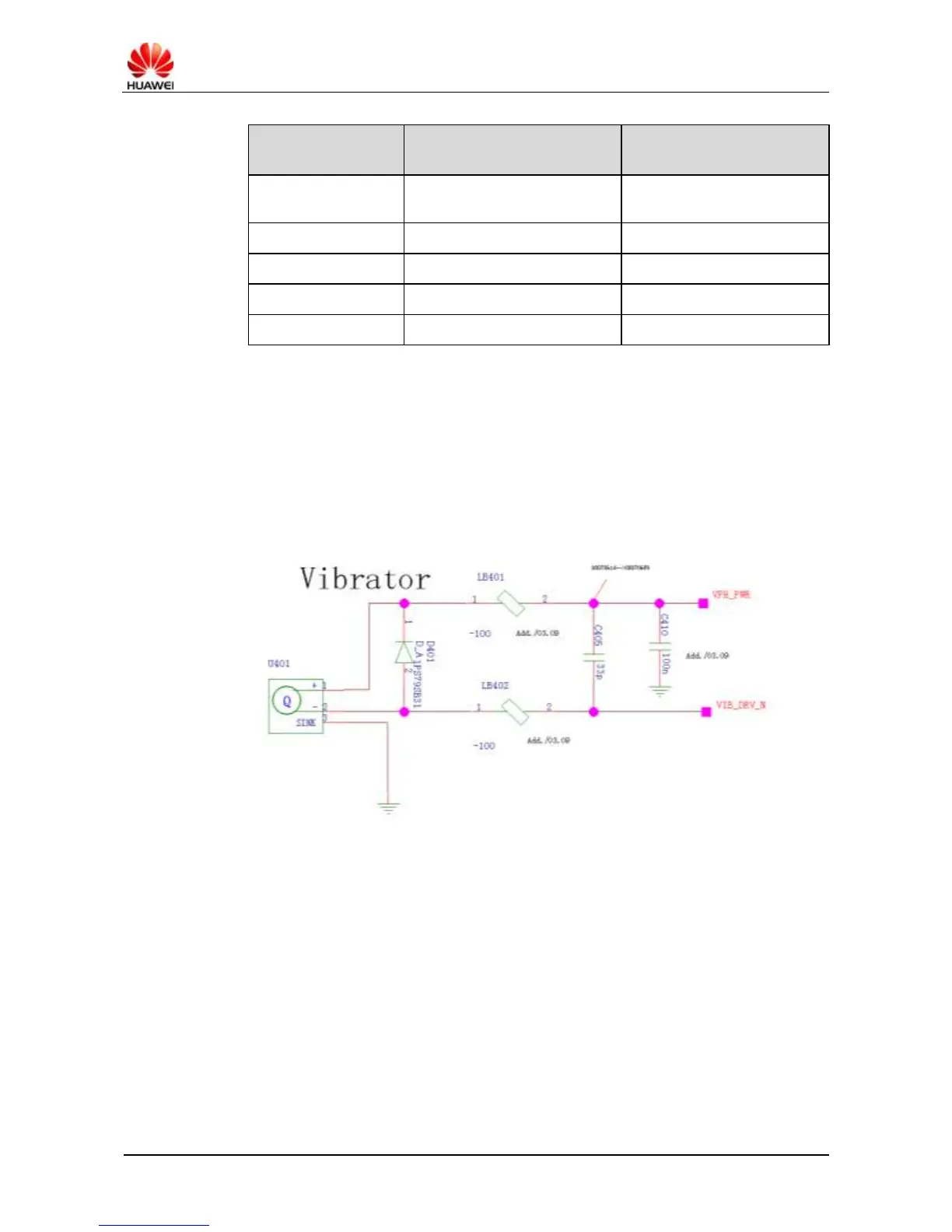
Figure 9-26 shows the vibrator circuit diagram.
Figure 9-26 Vibrator circuit diagram
Analysis
The PM8029's VIB_DRV_N pin serves as the drive pin of the vibrator and is located on the
main PCB. When the vibrator is not vibrating, the level VPH_PWR and VIB_DRV_N is high.
Troubleshooting
Fault symptom: The vibrator does not vibrate.
Handling: Troubleshoot the fault according to the process shown in Figure 9-27.

Related product manuals