EasyManua.ls Logo

Huawei G510 - Headset Circuit

Huawei G510
96 pages
Print Icon
To Next Page IconTo Next Page
To Previous Page IconTo Previous Page
Loading...
G510 Maintenance Manual V1.0
INTERNAL
2013-01-28
Page 72 of 96
Circuit Symbols
Signal Symbol
Description
Reference Measurement or
Waveform
MIC1_P
Primary microphone input
None
MIC1_N
Primary microphone input
None
AUXI_P
Secondary microphone input
None
AUXI_N
Secondary microphone input
None
MSM_MICBIAS
Bias voltage of the primary
microphone
None
SND_MICBIAS
Bias voltage of the secondary
microphone
None
9.4.5 Headset Circuit
Circuit Diagram
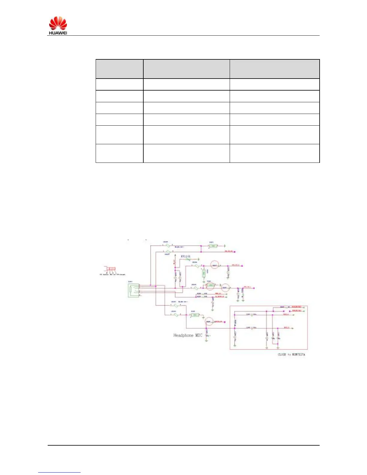
Figure 9-35 shows the headset circuit diagram.
Figure 9-35 Headset circuit diagram
Analysis
The headset is tested using the GPIO_026's HS_DETECT_N after being inserted to the G510:
Before the headset is inserted, HS_DETECT_N is converted to high level by VREG_S3.
After the headset is inserted, HS_DETECT_N is converted to low level.

Related product manuals