5
4
Electrical Connections
Preparing Cables
4.1
Recommended Specifications
Outdoor copper cable with a cross
-sectional area of 4–6 mm
2
RS485 communications cable
-core or multi-core cable with a cross-sectional area of 0.2–
-core or multi-core cable with a cross-sectional area of 0.2–
For details about the cables and cable connection operations,
see the documents
delivered with the PT100/PT1000.
-core cable with a cross-sectional area of 0.2–1.5 mm
2
or
–16 AWG
• Connect cables in accordance with the installation laws and regulations of the country or region
where the project is located.
• Before connecting cables to ports, leave enough slack to reduce the tension on the cables and
prevent poor cable connections.
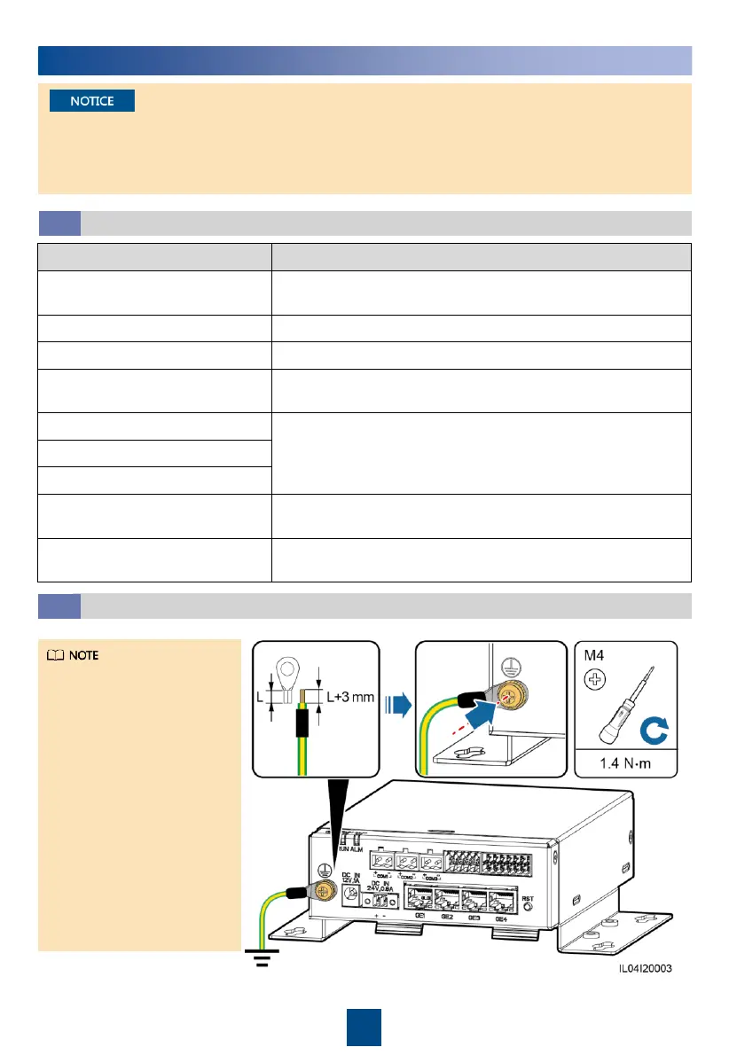
Connecting the PE Cable
4.2
• To enhance the
corrosion resistance of
the ground terminal,
you are advised to
apply silica gel or paint
on it after connecting
the ground cable.
• If the SmartLogger is
connected to the
SmartModule over a
connecting plate,
connect a PE cable to
the ground point of the
SmartLogger or
SmartModule based on
site requirements.